
Combination of tube assembly and clip for wireless antenna grounding

An antenna tube and grounding clip technology, which is used in antenna grounding devices, antenna connectors, antenna parts, etc.

Inactive Publication Date: 2006-01-04
RES IN MOTION LTD
View PDF0 Cites 2 Cited by
  • Summary
  • Abstract
  • Description
  • Claims
  • Application Information

AI Technical Summary

Problems solved by technology

If the antenna requires proper grounding in the fully retracted position, this axial movement moves the antenna from the fully retracted position, resulting in an ineffective ground
[0005] Another problem with retractable antennas is that they can transfer water into the antenna tube when they are moved from an extended to a retracted state, especially when the mobile device is used in the rain

Method used


Image

  • Combination of tube assembly and clip for wireless antenna grounding
  • Combination of tube assembly and clip for wireless antenna grounding
  • Combination of tube assembly and clip for wireless antenna grounding

Examples


Embodiment Construction

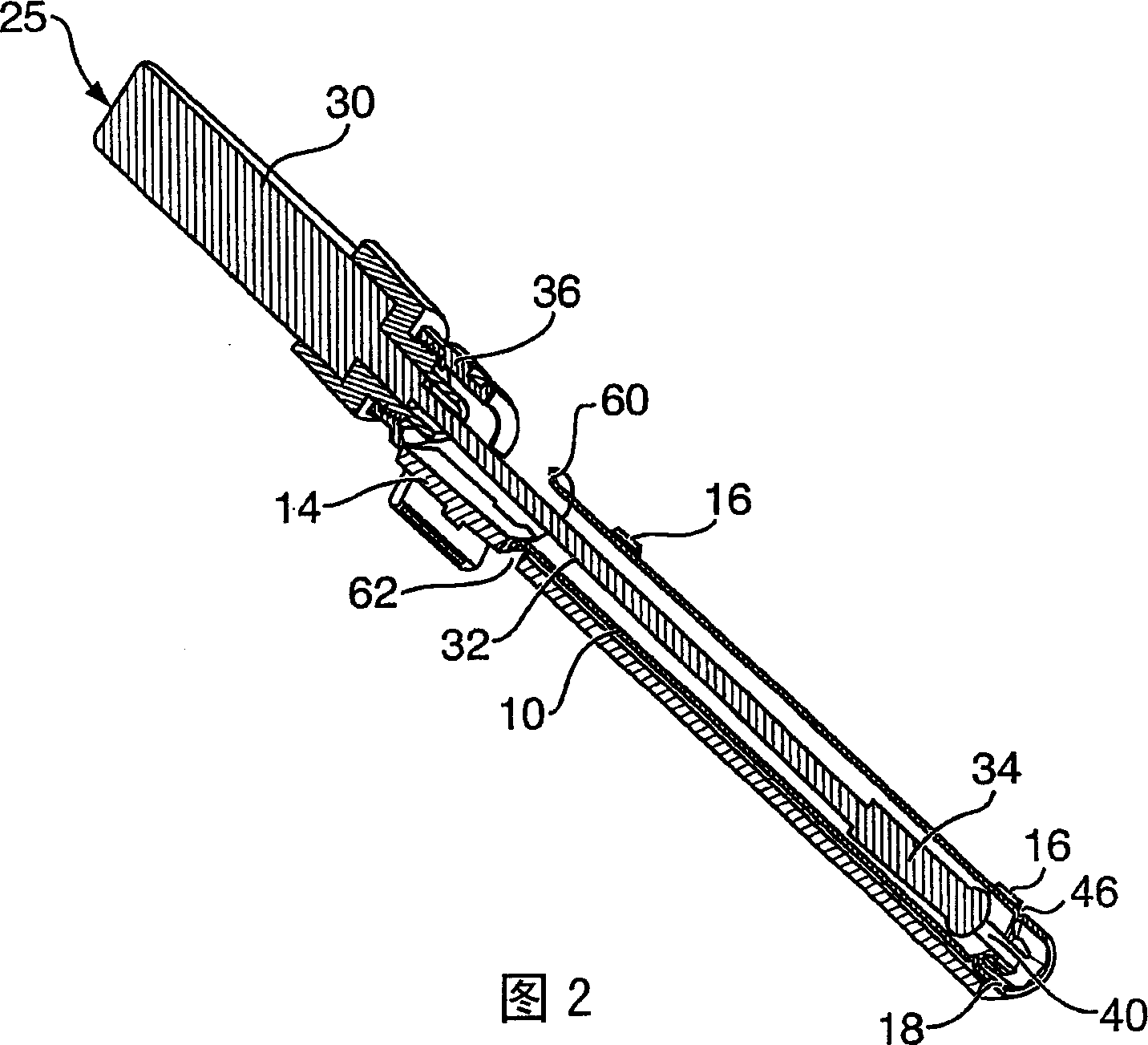
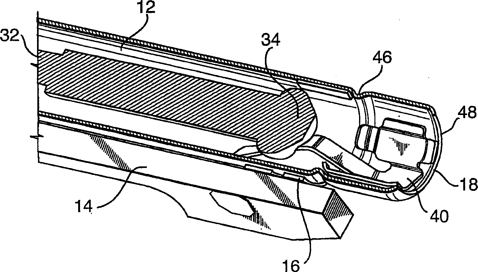
[0030] now refer to figure 1 and 2. figure 1 and 2 show the tubular assembly 10 for the retractable antenna 25. The tubular assembly 10 includes an outer metal wall 12 formed to a precise inner diameter that ensures small deviations.

[0031] Tube assembly 10 is mounted to printed circuit board (PCB) 14 using surface mount technology clips (SMT) 16 . The SMT clips provide electrical contact between the tube assembly 10 and the PCB 14 .

[0032] Antenna 25 includes an outer protective sheath 30 at the outer end of the antenna, an antenna shaft 32, and a contact block 34 (at image 3 see more clearly in ). The antenna 25 is held on the hand-held device at the upper end of the shaft using a fitting 36 . The fitting 36 provides stability to the antenna 25 and further provides weather protection for the tube assembly 10 to limit the ingress of water.

[0033] The user is able to extend the antenna 25 by pulling the cover 30 outwardly relative to the handheld device. This cau...


PUM


Abstract

An antenna grounding assembly for a hand-held device, the grounding assembly comprising: an antenna having an antenna shaft connected between a grounding block and a protective sheath; an antenna tube affixed within the hand-held device and holding the antenna, the antenna tube having an upper end through which the antenna shaft is extended or retracted, and an inner end opposite the upper end; and a grounding clip installed into the inner end of the antenna tube, the grounding clip having a base and at least one contact pin extending axially along the antenna tube for resilient contact with the grounding block.

Description

technical field [0001] The present invention relates to antenna grounding and mounting techniques, and in particular to antenna mounting and grounding in mobile devices. Background technique [0002] To maximize signal reception and minimize noise, good grounding of the antenna is required. Unfortunately, in many mobile devices where the antenna is stored in a retracted state, proper grounding is not achieved. This is generally the result of improper contact between the antenna contact block and ground in the antenna tube assembly. [0003] Further, even when the antenna has a ground in the fully retracted position, in many cases the ground is ineffective when the antenna is not fully retracted. This can happen if the user does not push the antenna all the way into its fitting, but instead lets it partially extend. [0004] Another problem with current grounding technology occurs during assembly of the antenna that the assembly tube can move axially. If the antenna requi...

Claims


Application Information

Patent Timeline
IPC IPC(8): H01Q1/24H01Q1/48H01R4/48H01R13/115H01R4/64H01R13/03H01R13/187
CPCH01Q1/242H01Q1/244H01Q1/48H01R13/187H01R13/03H01R2201/02H01R4/64
Inventor 陈超蒂莫西·H·基奥斯基
Owner RES IN MOTION LTD
Learn More