Eureka AIR delivers breakthrough ideas for toughest innovation challenges, trusted by R&D personnel around the world.

Control method of proportional electromagnetic type electron throttle and proportional electromagnet

A technology of proportional electromagnet and electronic throttle, applied in electromagnet, engine control, machine/engine, etc., can solve problems such as accidents, lack of automatic return function, slow response speed, etc., to achieve increased reliability, simple structure, fast response effect

Inactive Publication Date: 2006-01-11
广州多威服饰有限公司
View PDF0 Cites 4 Cited by
  • Summary
  • Abstract
  • Description
  • Claims
  • Application Information

AI Technical Summary

Problems solved by technology

The disadvantage of these two solutions is that the response speed is slow when the stroke of the throttle lever is long, and the stepping motor or DC motor is used when the car suddenly loses power, and it does not have the automatic return function, which may cause accidents.

Method used


Image

  • Control method of proportional electromagnetic type electron throttle and proportional electromagnet
  • Control method of proportional electromagnetic type electron throttle and proportional electromagnet
  • Control method of proportional electromagnetic type electron throttle and proportional electromagnet

Examples


Embodiment 1

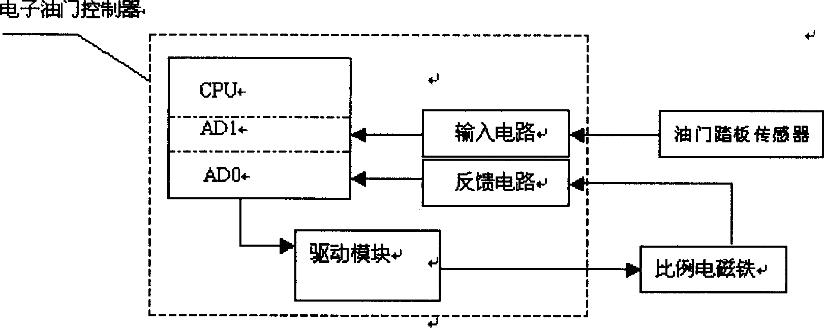
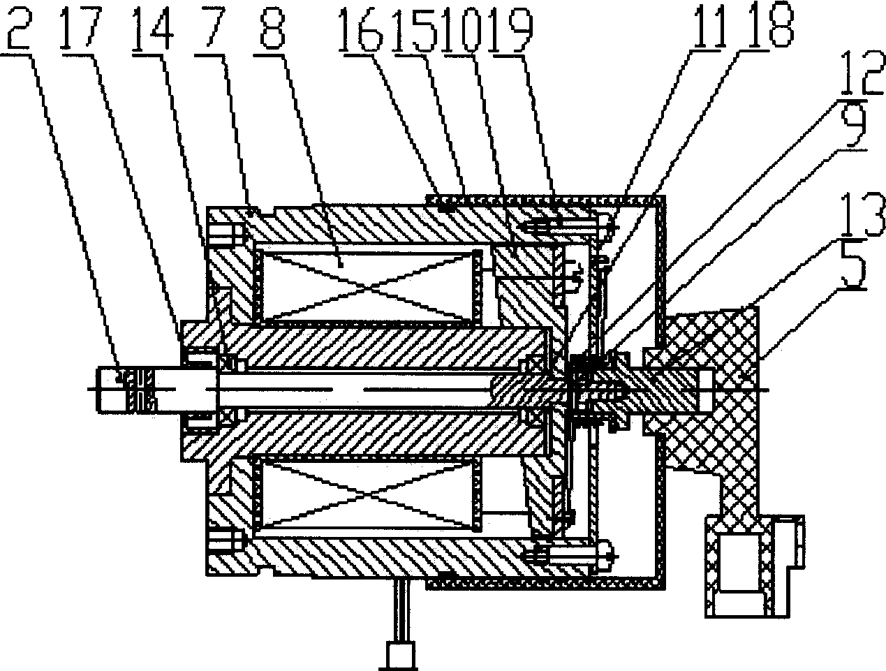
[0014] Embodiment 1 of the present invention: electronic throttle controller 6, connecting rod 3, throttle pull rod 4 and potentiometer 5 among the present invention all adopt the finished product that existing market sells, and throttle pull rod 4 is the throttle on the existing engine fuel injection pump tie rod. as attached Figure 4 As shown, the rotary proportional electromagnet 1 is installed at the position of the throttle lever of the fuel injection pump of the automobile engine, the rotary proportional electromagnet 1 is connected to the signal output end of the electronic throttle controller 6, and the shaft 2 of the rotary proportional electromagnet 1 is connected to the One end of the rod 3 is connected, and the other end of the connecting rod 3 is connected with the throttle rod 4; a potentiometer 5 is installed in the rotary proportional electromagnet 1, and the potentiometer 5 is connected to the signal input terminal of the electronic throttle controller 6. as...

Embodiment 2

[0016] Embodiment 2 of the present invention: a linear proportional electromagnet 21 is installed at the position of the throttle lever of the automobile engine, the linear proportional electromagnet 21 is connected to the signal output end of the electronic throttle controller 26, and the shaft 22 of the linear proportional electromagnet 21 It is connected with one end of the connecting rod 23, and the other end of the connecting rod 23 is connected with the throttle pull rod 24; a potentiometer 25 is installed in the linear proportional electromagnet 21, and the potentiometer 25 is connected to the signal input end of the electronic throttle controller 26. Can. During work, the accelerator sensor transmits the accelerator pedal position signal to the analog-to-digital conversion module AD1 of the electronic accelerator controller 26 through the input circuit, and then transmits it to the CPU. After being processed by the CPU, the command signal is sent to the drive module thr...


PUM


Abstract

The invention discloses a proportional electromagnetic electronic throttle controlling method. An electronic throttle controller is used for controlling the movement of the throttle drawbar on the jet pump by proportional electromagnet, i.e. the signal of a throttle pedal sensor is input into the electronic throttle controller to be processed and the processed signal is output to the proportional electromagnet to drive the axial movement of the proportional electromagnet, so the throttle drawbar of the jet pump is powered by the proportional electromagnet to control the amount of the fuel in the jet pump. In the proportional electromagnet for controlling the throttle drawbar a spring or a torsional spring is set, so as to make the running more reliable.

Description

Technical field: [0001] The invention relates to a proportional electromagnet type electronic throttle control method for an electronically controlled throttle of an engine and a proportional electromagnet, belonging to the technical field of an electronically controlled throttle of an engine. Background technique: [0002] With the development of the modern automobile industry, it has become a trend in the development of the automobile industry to change the original mechanically controlled throttle to an electronically controlled throttle. The electronically controlled throttle can improve engine power, economy and emissions. The existing electronic throttle actuator has two forms of electric and pneumatic control. The two ends of the pneumatic actuator cylinder piston are respectively connected to the intake pipe and the atmosphere, and the average pressure in the cylinder is controlled by a pressure control valve; the motor actuator works by using the rotation of a DC mo...

Claims


Application Information

Patent Timeline
Patent Type & Authority Applications(China)
IPC IPC(8): F02D11/10H01F7/06
Inventor 周力敖成丽侯贻真林洁
Owner 广州多威服饰有限公司
Why Eureka
Eureka Blog
Learn More