

Zero gap speed changing mechanism
A speed change mechanism, no gap technology, applied in mechanical equipment, transmission parts, belts/chains/gears, etc., can solve the problems of small driving torque, reduced robot operation accuracy, high price, etc., and achieve the effect of high transmission accuracy
Image

Examples
Embodiment 1
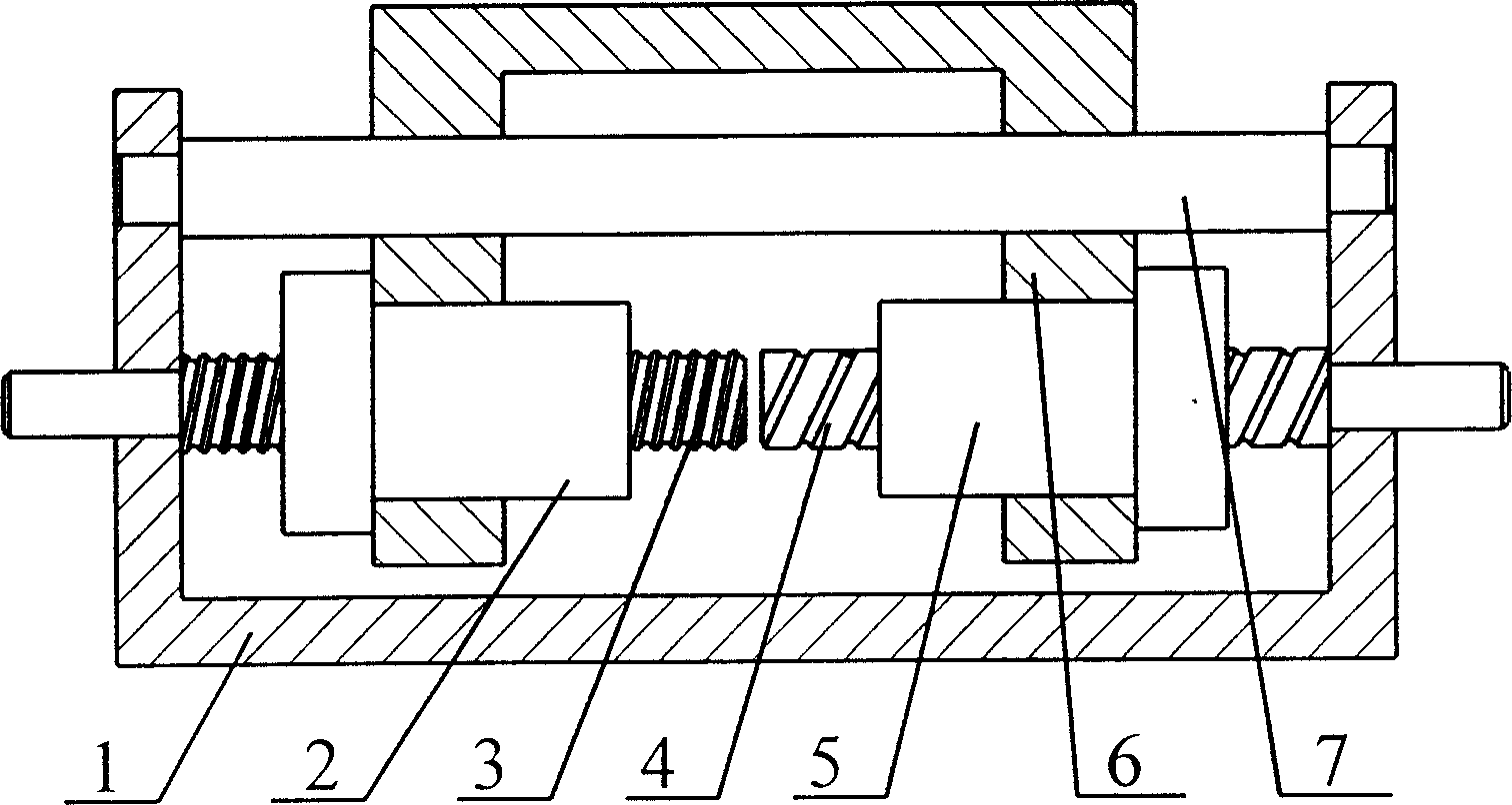
[0014] figure 1 Two rolling screw screws (3) and (4) and guide rails (7) with different leads are installed in parallel on the upper axis of the support (1) of a kind of gapless transmission mechanism of the present invention, and the rolling screw screws (3) and ( 4) Install the pre-tightening nuts (2) and (5) respectively, the transmission block (6) installed on the guide rail (7) is connected with the pre-tightening nuts (2) and (5), and the two rolling screws (3) It is coaxial with the axis of (4).
[0015] figure 1 The working principle of the gapless transmission mechanism of the present invention shown is: if the rolling screw (3) turns, the preload nut (2) moves left and right, driving the transmission block (6) and the preload nut (5) along the guide rail (7) Move left and right, and the left and right movement of the pre-tightening nut (5) makes the rolling screw (4) rotate. If the leads of the rolling screw (3) and the rolling screw (4) are different, the rotatio...
Embodiment 2
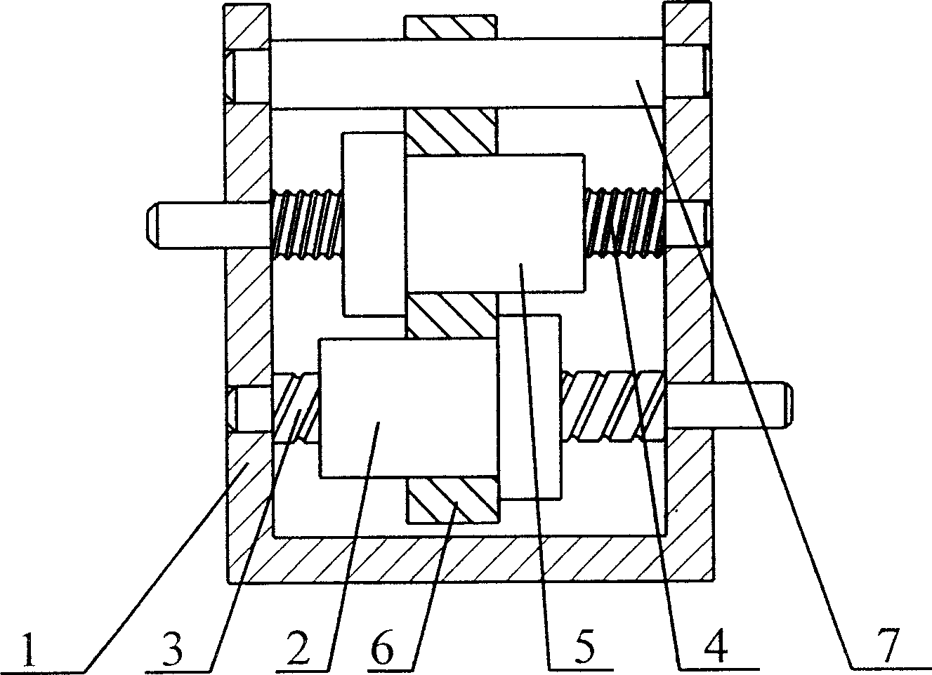
[0017] figure 2 Two rolling screw screws (3) and (4) and guide rails (7) with different leads are installed in parallel on the upper axis of the support (1) of a kind of gapless transmission mechanism of the present invention, and the rolling screw screws (3) and ( 4) Install the pre-tightening nuts (2) and (5) respectively, the transmission block (6) installed on the guide rail (7) is connected with the pre-tightening nuts (2) and (5), and the two rolling screws (3) And the axis of (4) is different from the axis.
[0018] figure 2 The working principle of the gapless transmission mechanism of the present invention shown is: if the rolling screw (3) turns, the preload nut (2) moves left and right, driving the transmission block (6) and the preload nut (5) along the guide rail (7) Move left and right, and the left and right movement of the pre-tightening nut (5) makes the rolling screw (4) rotate. If the leads of the rolling screw (3) and the rolling screw (4) are differen...
PUM
 Abstract
Description
Claims
Application Information
- IPC
- F16H25/20; F16H57/00
- Inventors
- 李为民; 张建军