
Induction motor controller

A technology of motor controller and induction motor, which is applied in control system, starter of a single single-phase induction motor, motor generator control, etc., and can solve the problem that the induction motor cannot be driven quickly

Inactive Publication Date: 2006-01-11
LG ELECTRONICS INC
View PDF2 Cites 2 Cited by
  • Summary
  • Abstract
  • Description
  • Claims
  • Application Information

AI Technical Summary

Problems solved by technology

However, when the induction motor is initially driven, since the current applied to the stator is smaller than the current required for driving, the magnetomotive force decreases, and because the magnetomotive force decreases, the induction motor cannot be driven quickly in the initial stage

Method used


Image

  • Induction motor controller
  • Induction motor controller
  • Induction motor controller

Examples


Embodiment Construction

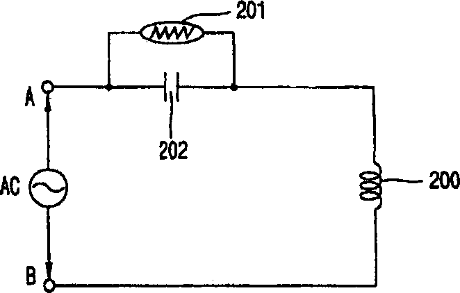
[0028] Below, refer to Figure 3 to Figure 8B , a preferred embodiment of an induction motor controller capable of rapidly driving the induction motor at an initial stage and capable of driving the induction motor with high efficiency and low power consumption after rapidly driving the induction motor at the initial stage is introduced in detail. The structure of the induction motor according to the present invention is the same as the structure of the induction motor of the prior art, and thus its related detailed description is omitted. Furthermore, in the structure of the induction motor of the present invention, which is the same as that of the conventional induction motor, the same reference numerals as those of the conventional induction motor are used.

[0029] image 3 It is a structural schematic diagram of the induction motor controller according to the first embodiment of the present invention.

[0030] Such as image 3 As shown, the induction motor controller ac...


PUM


Abstract

The present invention provides a motor controller including a first capacitor connected in series with stator coils of the motor and a PTC thermistor (Positive Temperature Coefficient thermistor) connected in parallel with the first capacitor. It is capable of swiftly driving a motor at the initial stage and driving the motor with high efficiency and low power consumption after swiftly driving the motor at the initial stage.

Description

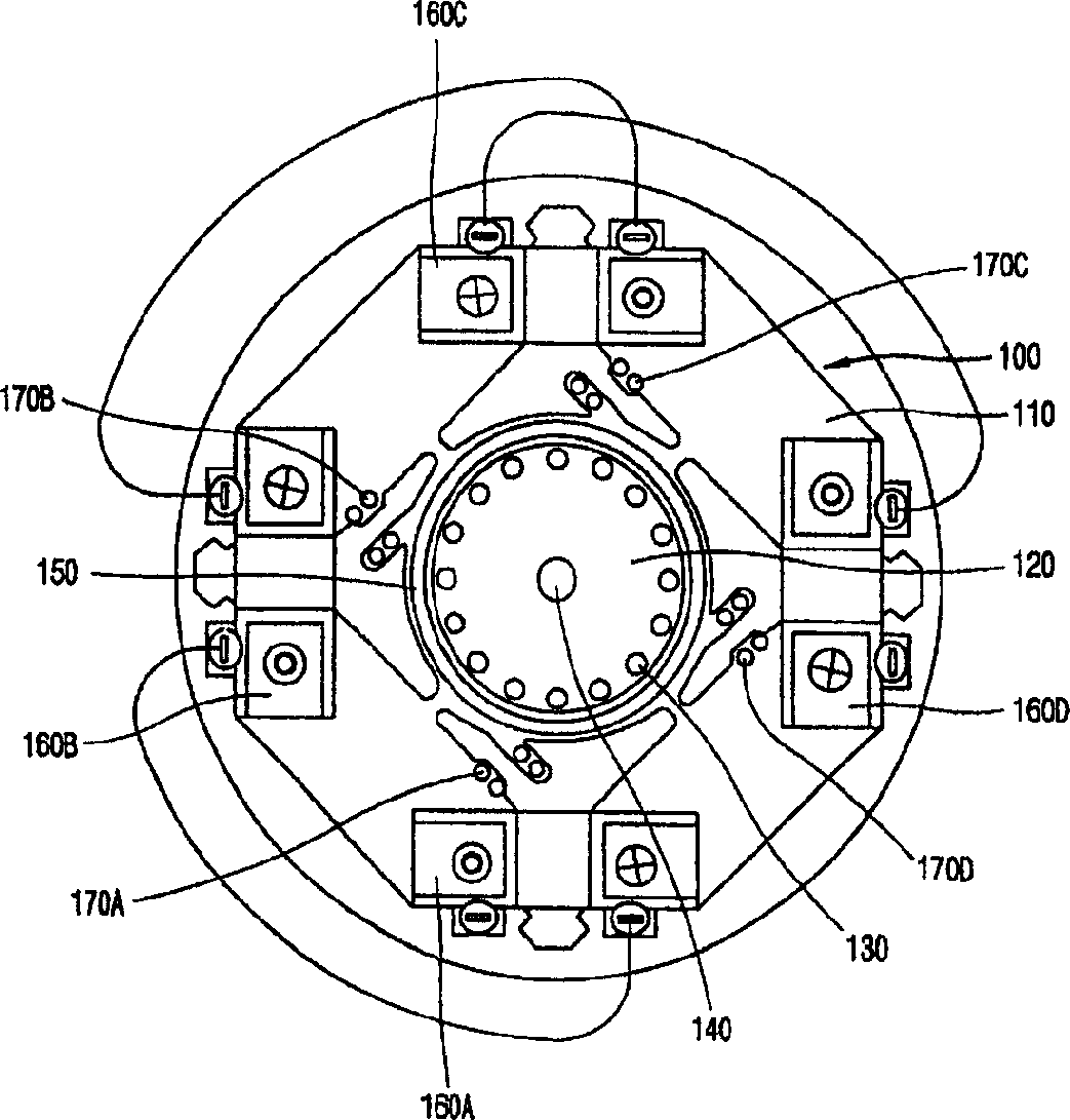
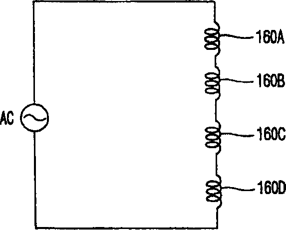
technical field [0001] The present invention relates to an induction motor, and more particularly to an induction motor controller. Background technique [0002] figure 1 It is a structural schematic diagram of an induction motor according to the prior art. [0003] Such as figure 1 As shown, the induction motor according to the prior art mainly includes: a stator 100 ; an induction rotor 120 ; a permanent magnet rotor 150 ; and a rotating shaft 140 . [0004] The stator 100 is composed of four stator coils 160A, 160B, 160C and 160D which are respectively wound on the iron core 110 of the induction motor. Meanwhile, in order to generate an elliptical rotating magnetic field in the stator 100, four correction coils (shading coils) 170A, 170A, 170B, 170C and 170D. Here, the four stator coils 160A, 160B, 160C, and 160D are sequentially connected in series so that coils adjacent to each other have the same polarity. [0005] The permanent magnet rotor 150 includes ring-sha...

Claims


Application Information

Patent Timeline
IPC IPC(8): H02K11/00H02P1/00H02P1/42H02P1/44H02P25/04
CPCH02P25/04H02P1/42H02P1/44
Inventor 韩承道申铉定
Owner LG ELECTRONICS INC
Learn More