Self-drive circuit for switch power supply

A switching power supply and self-driven technology, which is applied in the direction of electrical components, electric variable adjustment, output power conversion devices, etc., can solve the problems of high power density and low-cost design of isolation drive transformers, etc.

Inactive Publication Date: 2006-01-18
YIBO POWER SUPPLY CO LTD HANGZHOU
View PDF0 Cites 17 Cited by
  • Summary
  • Abstract
  • Description
  • Claims
  • Application Information

AI Technical Summary

Problems solved by technology

This solution solves the drive of the active clamp tube, but this drive circuit transmits the entire PWM signal from the primary side of the isolation drive transformer to the secondary side to realize the shutdown and opening of the active clamp tube S2. The isolation drive transformer needs transfer power, therefore, the volume of the isolation drive transformer is difficult to make small
In small to medium power applications, this makes high power density difficult to achieve, and the cost of the isolation drive transformer makes low cost designs difficult

Method used


Image

  • Self-drive circuit for switch power supply
  • Self-drive circuit for switch power supply
  • Self-drive circuit for switch power supply

Examples


Embodiment Construction

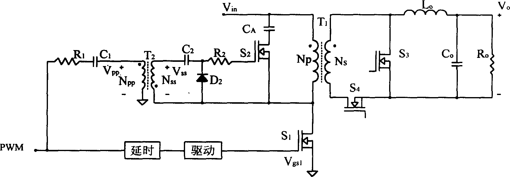
[0023] Fig. 1(a) shows the drive circuit of a clamp tube in a commonly used active clamp forward converter. Its defects have been described above and will not be repeated here.

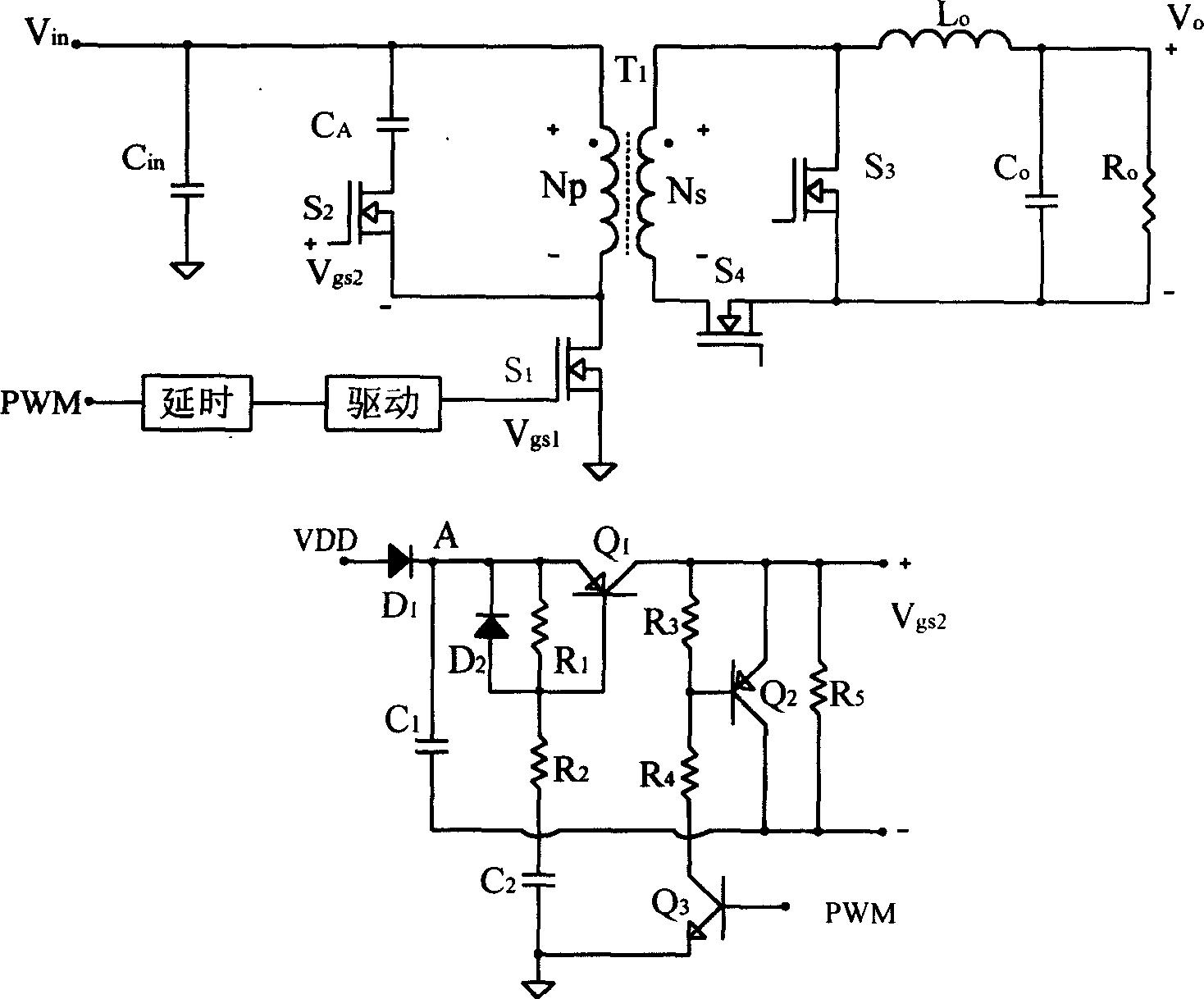
[0024] refer to Figure 2a , the self-driving circuit of the present invention is applied in an active clamp forward converter. The converter has the primary winding Np of the main transformer, the secondary winding Ns, the main power MOS transistor S1 of the primary side, the active clamping transistor S2, and the active clamping capacitor C A , input capacitor Cin, secondary side rectification power MOS tube S3, freewheeling power MOS tube S4, output filtering inductance Lo, output capacitor Vo; the non-identical end of the primary side winding Np and the drain of the primary side main power MOS tube S1 The pole is connected to the source of the active clamp tube S2; the active clamp capacitor C A One end of the primary winding is connected to the same-named end of the primary winding, and the oth...


PUM


Abstract

This invention relates to an automatic drive circuit for power switch, whose changer circuit comprises main horsepower MOSFET, synchronous rectifying tube, and the said automatic drive circuit comprises a time-delay drive circuit with its two ends separately attached to PWM signal and main power tube, a cut-out circuit including a PNP transistor, a NPN transistor and two electric resistance, a drive sustaining circuit including two diodes, three electric resistances, two capacitors and a PNP transistor. The invention makes the high power density and low cost design easier in the case of low power application.

Description

technical field [0001] The invention relates to a switching power supply, in particular to a novel self-driving circuit of an active clamp tube or a synchronous rectifier tube of a switching power supply. Background technique [0002] High efficiency is always an important indicator of switching power supply design. In order to achieve high efficiency, active clamping and synchronous rectification techniques are widely used. However, the driving of the clamp tube in the active clamp circuit or the synchronous rectification tube in the converter using synchronous rectification technology has become a difficult problem for designers. The present invention introduces a self-driving circuit by taking an active clamp forward converter as an example. [0003] Figure 1(a) shows the drive circuit of an active clamp tube in a commonly used active clamp forward converter. The main circuit of the converter includes a primary power circuit and a secondary circ...

Claims


Application Information

Patent Timeline
Patent Type & Authority Applications(China)
IPC IPC(8): H02M3/335
Inventor 刘亚李斌华桂潮
Owner YIBO POWER SUPPLY CO LTD HANGZHOU
Why Eureka
Try Eureka