Flyback circuit, control method thereof and control circuit

A flyback circuit and control method technology, applied in control/regulation systems, high-efficiency power electronic conversion, electrical components, etc., can solve problems such as low driving voltage and efficiency loss, prevent the common of primary and secondary sides, and improve system reliability. performance, optimizing system efficiency

Active Publication Date: 2021-02-09
JOULWATT TECH INC LTD
View PDF5 Cites 4 Cited by
  • Summary
  • Abstract
  • Description
  • Claims
  • Application Information

AI Technical Summary

Problems solved by technology

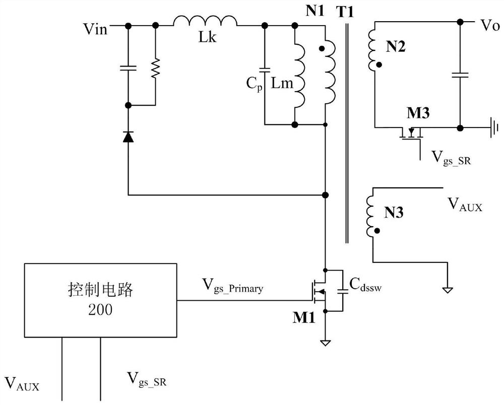
[0005] In view of this, the purpose of the present invention is to provide a flyback circuit and its control method and control circuit to solve the problem in the prior art that the current flowing through the synchronous rectifier becomes smaller and the driving voltage becomes lower. Loss problem, and optimize the system efficiency of the main switch tube zero voltage turn-on

Method used


Image

  • Flyback circuit, control method thereof and control circuit
  • Flyback circuit, control method thereof and control circuit
  • Flyback circuit, control method thereof and control circuit

Examples


Embodiment Construction

[0027] Preferred embodiments of the present invention will be described in detail below with reference to the accompanying drawings, but the present invention is not limited to these embodiments. The present invention covers any alternatives, modifications, equivalent methods and schemes made within the spirit and scope of the present invention.

[0028] In order to provide the public with a thorough understanding of the present invention, specific details are set forth in the following preferred embodiments of the present invention, but those skilled in the art can fully understand the present invention without the description of these details.

[0029] In the following paragraphs the invention is described more specifically by way of example with reference to the accompanying drawings. It should be noted that all the drawings are in simplified form and use inaccurate scales, which are only used to facilitate and clearly assist the purpose of illustrating the embodiments of t...


PUM


Abstract

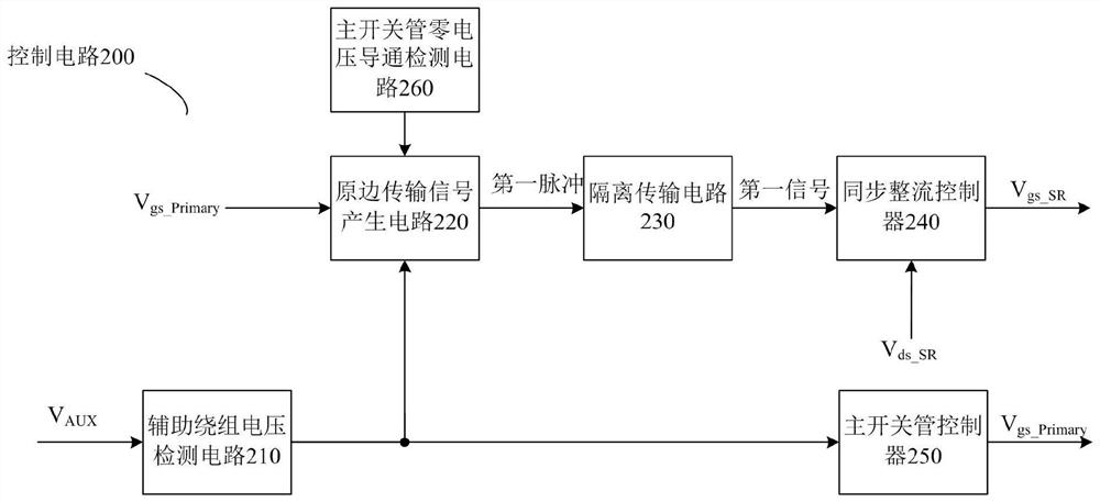
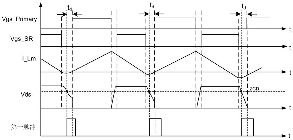
The invention discloses a control method for a flyback circuit, a control circuit and the flyback circuit. The flyback circuit comprises a main switch tube, a synchronous rectifier tube and a transformer, wherein the primary side of the flyback circuit generates a first pulse and transmits the first pulse to the secondary side, and the width of the first pulse controls the turn-off time of the synchronous rectifier tube. According to the invention, the system efficiency is optimized, interlocking of primary side driving and secondary side driving is realized, primary side and secondary side sharing is prevented, and the system reliability is improved.

Description

technical field [0001] The invention relates to the technical field of power electronics, in particular to a flyback circuit, a control method and a control circuit thereof. Background technique [0002] Because the existing synchronous rectifier controller cannot absolutely avoid the commonality of the primary and secondary sides from the mechanism, the control method of the synchronous rectifier controller starts to reduce the driving voltage when the current flowing through the synchronous rectifier tube becomes smaller, thereby reducing the continuous conduction common time in the mode. However, reducing the driving voltage will also result in a loss of efficiency. [0003] In traditional flyback converters, the main switching tube on the primary side is hard-turned-on, and the turn-on loss is large. As the adapter has higher and higher requirements for small size and high power density, the switching frequency needs to be increased, but the turn-on loss will be furthe...

Claims


Application Information

Patent Timeline
Patent Type & Authority Applications(China)
IPC IPC(8): H02M3/335H02M1/08H02M1/38
CPCH02M3/33592H02M1/08H02M1/38Y02B70/10
Inventor 许祥勇
Owner JOULWATT TECH INC LTD
Why Eureka
Try Eureka