Miniature hydro-power generation system

A technology for generators and shells, applied in the field of hydroelectric power generation, which can solve the problems of high cost, difficulty, and time-consuming installation of switchboards and/or cables

Inactive Publication Date: 2006-01-18
ACCESS BUSINESS GRP INT LLC
View PDF0 Cites 7 Cited by
  • Summary
  • Abstract
  • Description
  • Claims
  • Application Information

AI Technical Summary

Problems solved by technology

Where automatic plumbing fixtures are installed in existing buildings, installation of distribution panels and / or cabling is costly, time consuming and difficult

Method used


Image

  • Miniature hydro-power generation system
  • Miniature hydro-power generation system
  • Miniature hydro-power generation system

Examples


Embodiment Construction

[0045] Exemplary embodiments of the present invention are described below with reference to specific structures, and it will be understood by those skilled in the art that various changes and modifications can be made to these specific structures without departing from the scope of the claims. The presently preferred embodiments can be used with any water treatment system that requires power and includes water flow; however, these embodiments are designed for residential or mobile use. Those skilled in the art will also understand that these embodiments may be used with fluids other than water and the use of the terms "water" and "hydro" should not be considered a limitation.

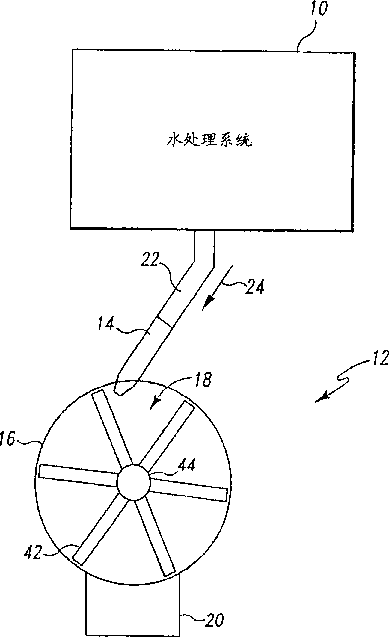
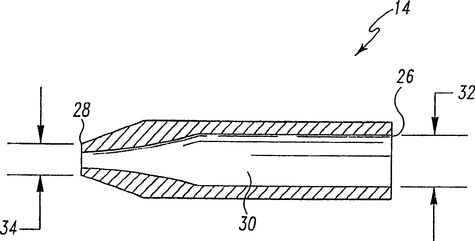
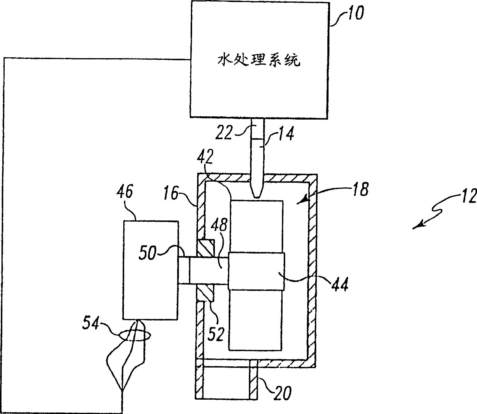
[0046] figure 1 Is a side view of a water treatment system 10 connected to a preferred hydroelectric power generation system 12 . In this embodiment, a hydroelectric power generation system 12 includes a nozzle 14 , a casing 16 , an impeller 18 and a casing outlet 20 . The nozzle 14 is connected to th...


PUM


Abstract

A miniature hydro-power generation system may produce electric power from a flow of liquid. The miniature hydro-power generation system may include a housing that includes a plurality of paddles positioned to extend outwardly from an outer surface of the housing. The system may also include a nozzle and a centering rod extending through the housing. The housing may rotate around the centering rod when a stream of liquid from the nozzle is directed at the paddles. A generator that includes a rotor and a stator may be positioned within a cavity of the housing. The rotor may be coupled with the housing and the stator may be coupled with the centering rod. The rotor may rotate around the stator at high RPM to generate electric power when the housing rotates. The electric power may supply a load and / or may be stored in an energy storage device.

Description

technical field [0001] The present invention relates generally to power generation, and more particularly to hydroelectric power generation with small hydroelectric power generation systems. Background technique [0002] Hydropower is known, in which kinetic energy is extracted from flowing pressurized water and used to turn an electrical generator to generate electrical power. In addition, it is known to use pressurized fluids such as gas, steam, etc. to rotate electrical generators. For large-scale hydroelectric power, which operates from large-scale water sources such as rivers or dams, millions of gallons of flowing water can be used to generate tens of thousands of megawatts of electrical energy. Thus, converting kinetic energy in flowing water to electrical energy may involve significant inefficiencies and may not provide economical and acceptable levels of performance. [0003] As the size of hydroelectric generating equipment becomes smaller, the amount of electric...

Claims


Application Information

Patent Timeline
Patent Type & Authority Applications(China)
IPC IPC(8): F03B13/06H02K7/18E03C1/12F03B13/00
CPCY02B10/50Y02E60/17Y02E10/223F03B13/00H02K7/1823Y02E10/28F05B2220/602Y02E10/20Y02E60/16F03B13/06H02K7/18E03C1/12
Inventor D·W·巴曼T·L·劳珍黑塞尔
Owner ACCESS BUSINESS GRP INT LLC
Why Eureka
Try Eureka