Apparatus for separating dust from vacuum cleaner

A dust separation and vacuum cleaner technology, applied in suction filters, swirl devices, etc., can solve the problems of large airflow loss, high motor power, and high use cost, and achieve the effect of improving vacuum degree and facilitating modeling and design.

Active Publication Date: 2006-01-25
ECOVACS ROBOTICS (SUZHOU ) CO LTD
View PDF1 Cites 4 Cited by
  • Summary
  • Abstract
  • Description
  • Claims
  • Application Information

AI Technical Summary

Problems solved by technology

But this kind of setting including two-stage cyclone makes it consume more energy in the process of separating dust, so the power of the correspondingly set motor is also larger, resulting in higher cost

Method used


Image

  • Apparatus for separating dust from vacuum cleaner
  • Apparatus for separating dust from vacuum cleaner
  • Apparatus for separating dust from vacuum cleaner

Examples


Embodiment Construction

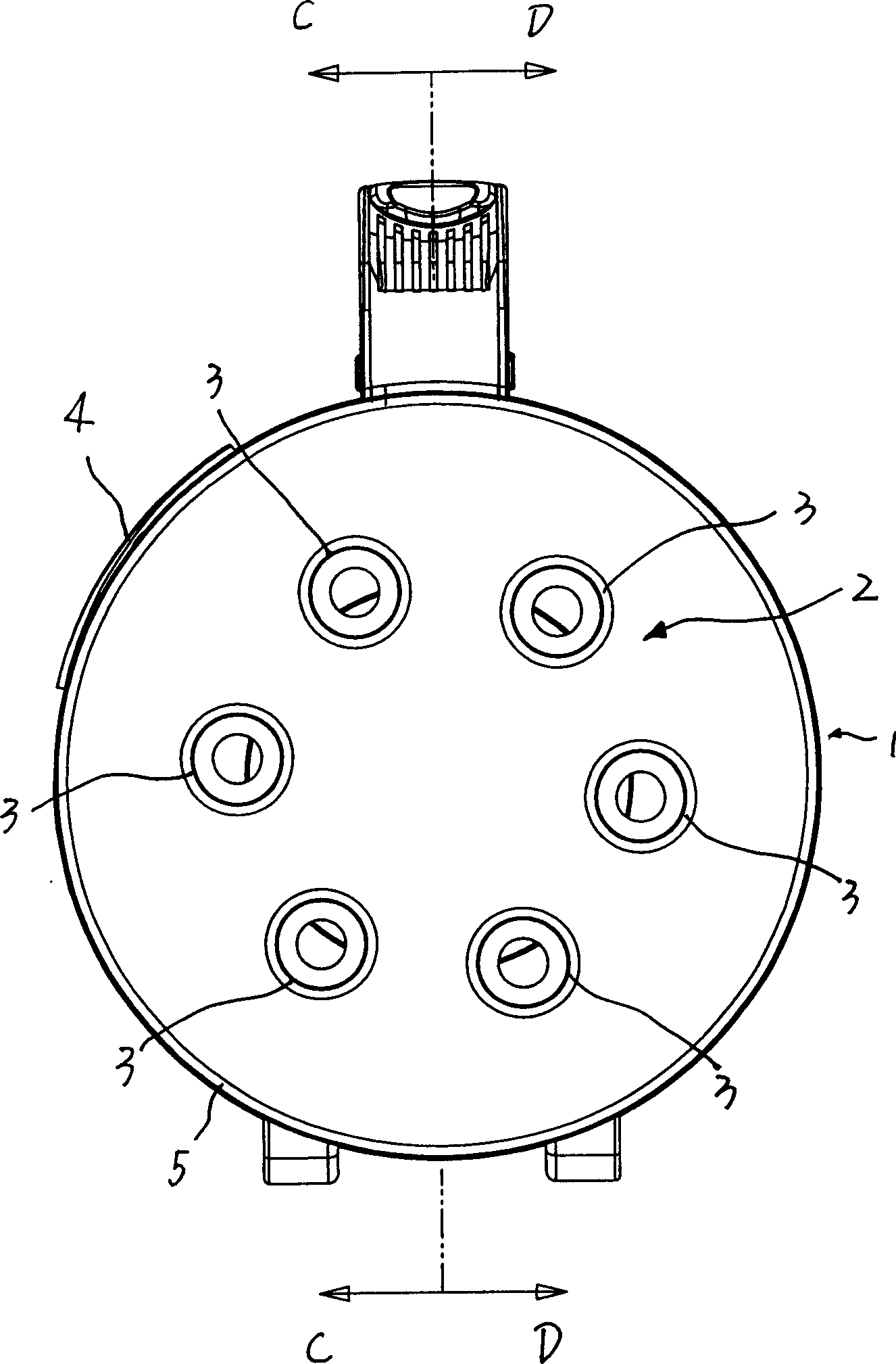
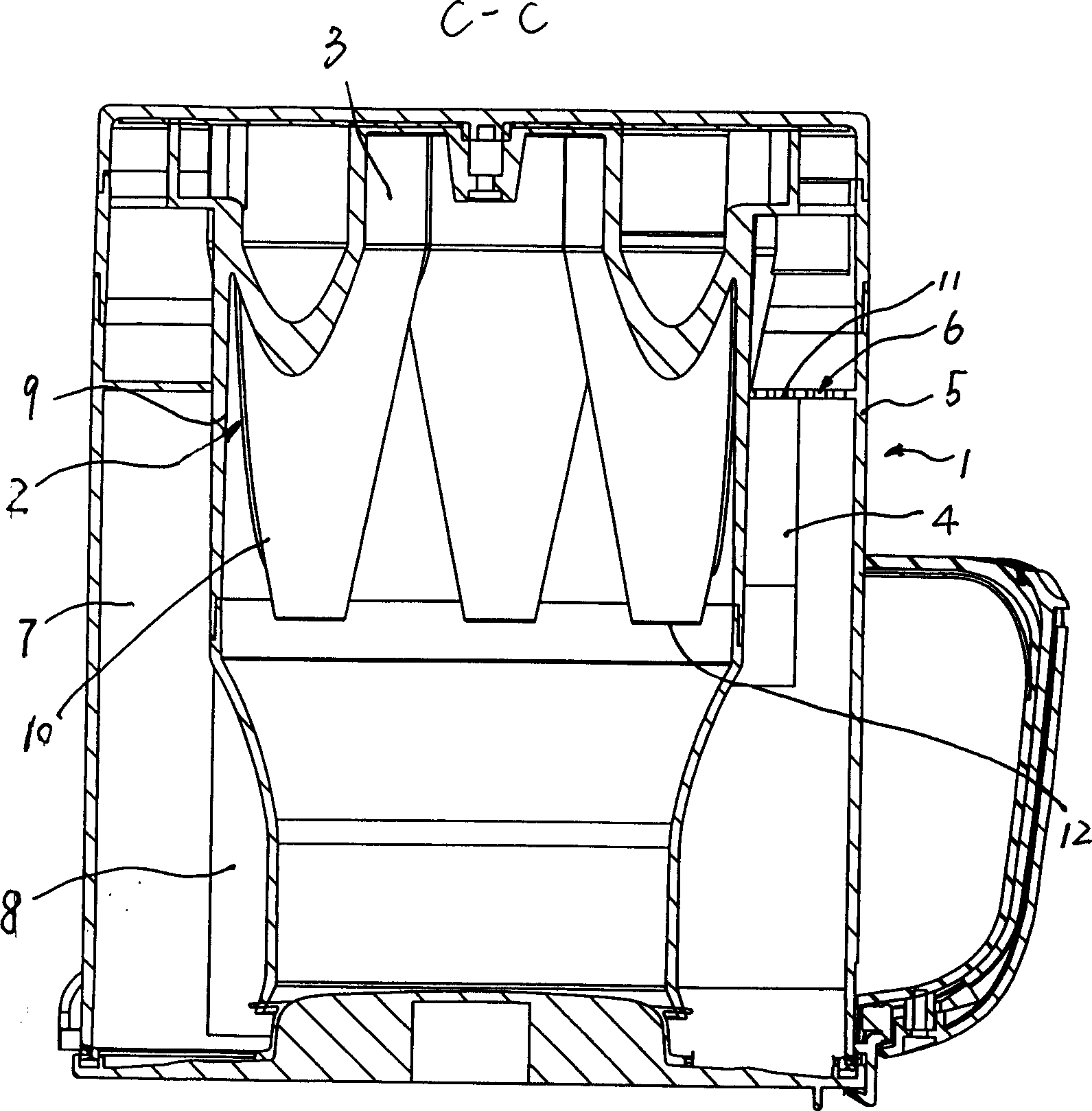
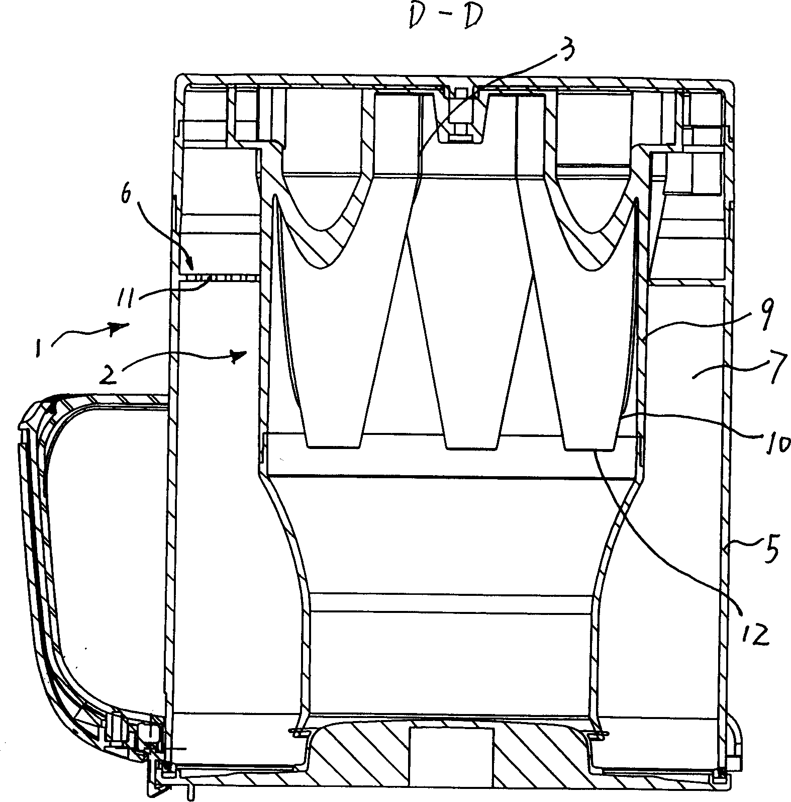
[0013] See attached figure 1 - attached Figure 6 , a dust separation device on a vacuum cleaner, comprising an upstream separator 1 located upstream and a downstream separator 2 located downstream, the upstream separator 1 is an inertial separator, and the downstream separator 2 is a cyclone separator , said downstream separator 2 at least partly protrudes into said upstream separator 1 . After the upstream separator 1 separates the large particles of dust, the airflow enters the downstream separator 2 to separate the small particles of dust.

[0014] The downstream separator 2 includes a plurality of cyclone separators 3 arranged side by side, and each cyclone separator 3 at least partially extends into the upstream separator 1 .

[0015] The upstream separator 1 has an air flow channel 7, as an inertial separator, the air flow channel 7 is provided with an air flow baffle 8 along its cross-sectional direction, so that the large particles of dust in the air flow collide wi...


PUM


Abstract

A dust separator unit of vacuum cleaner is composed of an upstream inertial separator with less energy consumption and a downstream cyclone separator in which part of said upstream inertial separator is extended.

Description

technical field [0001] The invention relates to a dust separating device on a vacuum cleaner. Background technique [0002] In the prior art, the dust separation device on the vacuum cleaner usually includes a two-stage separator, such as the equipment provided by the invention patent 01807570.3, which includes an upstream cyclone separator and a plurality of downstream cyclone separators, and the air flow is between the upstream cyclone separator and the downstream cyclone separator. Cyclone separation is carried out in the separator, so that the dust is separated from the air flow, and in order to make the structure of the whole device compact, the downstream cyclone separator is inserted in the upstream cyclone separator. But this kind of setting including two-stage cyclone makes it consume more energy in the process of separating dust, so the power of the correspondingly set motor is also larger, resulting in higher cost of use, and due to the ...

Claims


Application Information

Patent Timeline
IPC IPC(8): A47L9/10B04C9/00
Inventor 钱东奇
Owner ECOVACS ROBOTICS (SUZHOU ) CO LTD
Why Eureka
Try Eureka