Combustion pressure detecting apparatus

A technology of combustion pressure and detection device, applied in the direction of measurement device, measurement of rapid changes, instruments, etc., can solve the problems of being easily affected by heat, unable to accurately detect combustion pressure, etc., and achieve the effect of improving detection accuracy

Inactive Publication Date: 2006-02-08
HONDA MOTOR CO LTD
View PDF2 Cites 8 Cited by
  • Summary
  • Abstract
  • Description
  • Claims
  • Application Information

AI Technical Summary

Problems solved by technology

Also, since the sensor output wire extends along the length of the plug hole in such a plug hole, the part of the sensor output wire exposed to high temperature becomes long and is easily affected by heat, so the combustion pressure may not be accurately detected

Method used


Image

  • Combustion pressure detecting apparatus
  • Combustion pressure detecting apparatus
  • Combustion pressure detecting apparatus

Examples


Embodiment Construction

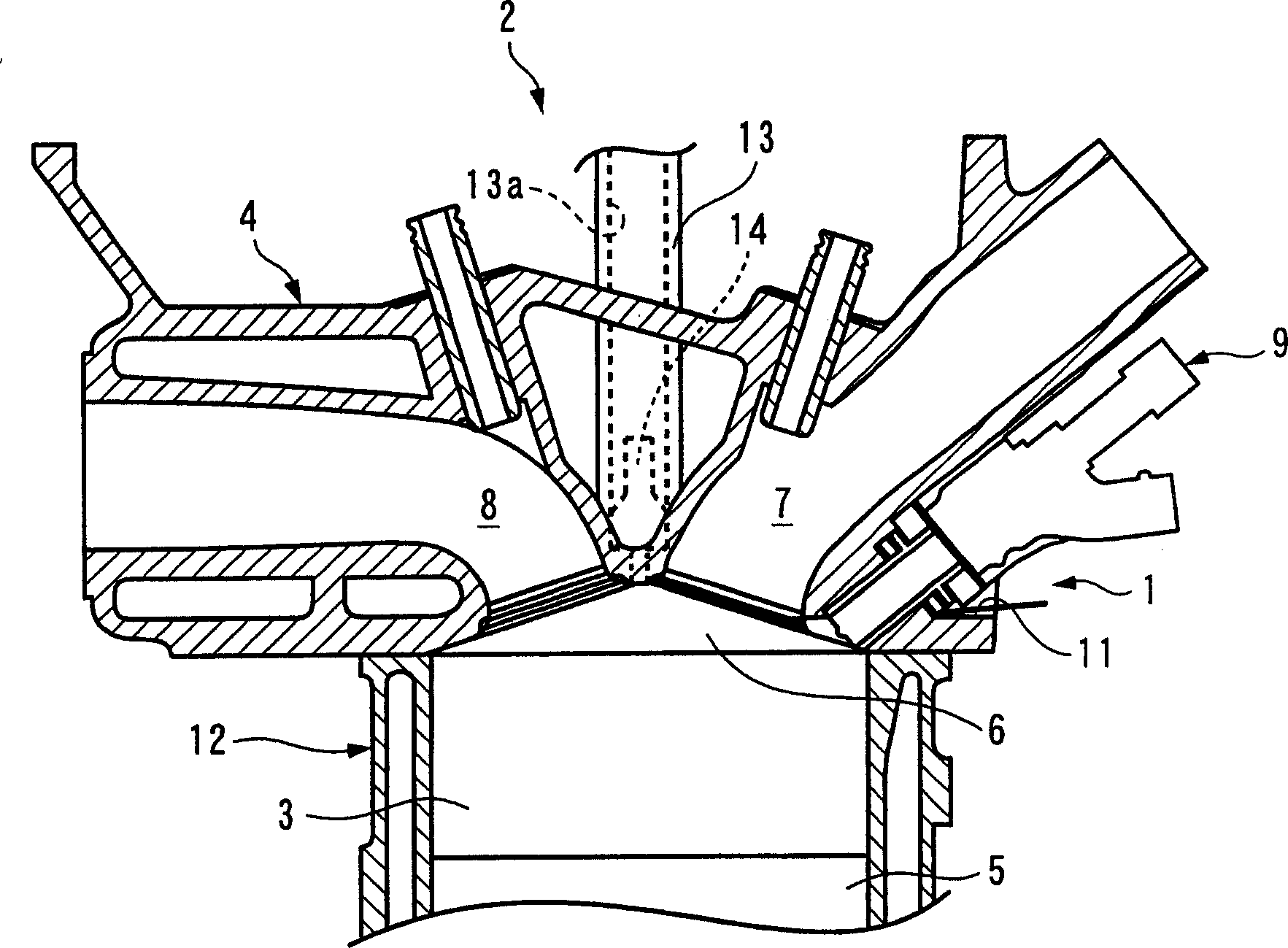
[0034] Hereinafter, embodiments of the present invention will be described in detail with reference to the drawings. figure 1 A combustion pressure detecting device 1 and an internal combustion engine (hereinafter referred to as "engine") 2 provided with the device 1 according to the first embodiment of the present invention are shown. The engine 2 is, for example, an inline four-cylinder direct injection engine mounted on a vehicle (not shown), and has a cylinder head 4 and a cylinder block 12 . Four cylinders 3 (only one is shown) are arranged in parallel on the cylinder block 12, and the cylinder head 4 is mounted on the top of the cylinder block 12, and the two cylinders 4, 12 are firmly joined to each other. A combustion chamber 6 is formed between the cylinder head 4 and the piston 5 in each cylinder 3 .

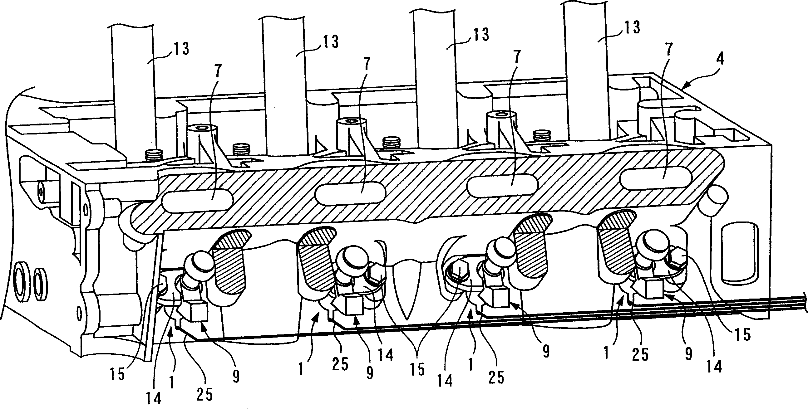
[0035] The cylinder head 4 is made of aluminum alloy, for example, and has figure 2 As shown in the complex shape, various constituent parts are installed. On the ...


PUM


Abstract

A combustion pressure detecting apparatus is provided for improving combustion pressure detection accuracy. The combustion pressure detecting apparatus is mounted in a mounting hole of a cylinder head together with a combustion device for detecting the pressure within a combustion chamber as a combustion pressure. The combustion device may be one of an injector for injecting a fuel and a spark plug for igniting an air / fuel mixture within the combustion chamber. The combustion pressure detecting apparatus comprises an injector seat facing the combustion chamber and arranged in the mounting hole in a state in which a load from the combustion device is blocked, and a sensor element fixed between injector seat and the cylinder head by the injector seat for detecting a load transmitted thereto through the injector seat as a combustion pressure.

Description

technical field [0001] The invention relates to a combustion pressure detection device installed on an internal combustion engine to detect the pressure in a combustion chamber. Background technique [0002] As a conventional combustion pressure detection device, for example, a device disclosed in Japanese Patent Application Laid-Open No. 10-18898 is known. This detection device is provided on a direct injection engine, and is constituted by an annular differential pressure sensor or the like sandwiched between an injector mounted on the cylinder head of the engine and a cylinder head. The injector is used to inject the fuel boosted to high pressure by the fuel pump into the combustion chamber, and its nozzle part faces the combustion chamber through the hole of the cylinder head. In addition, the differential pressure sensor is configured by a piezoelectric element or the like, and outputs a detection signal corresponding to a load acting thereon. According to the detecti...

Claims


Application Information

Patent Timeline
Patent Type & Authority Applications(China)
IPC IPC(8): G01L23/10F02D35/00
Inventor 沟吕木孝文沟田新中村胜则
Owner HONDA MOTOR CO LTD
Why Eureka
Try Eureka