Ambient light adaptation for dynamic foil displays

A display and optical display technology, used in static indicators, instruments, etc., can solve the problems of difficulty in providing images, limited number of gray levels, and inability to provide image quality, and achieve the effect of reducing motion artifacts and improving image quality.

Inactive Publication Date: 2006-02-08
KONINKLIJKE PHILIPS ELECTRONICS NV
View PDF1 Cites 10 Cited by
  • Summary
  • Abstract
  • Description
  • Claims
  • Application Information

AI Technical Summary

Problems solved by technology

[0008] However, experience has shown that the use of sub-fields to provide gray scale has certain limitations and drawbacks
For example, it struggles to provide a bright enough image for use in sunlight conditions
Furthermore, the limited number of gray levels available does not provide the desired image quality when used in dark ambient conditions
Additionally, severe artifacts can affect image quality

Method used


Image

  • Ambient light adaptation for dynamic foil displays
  • Ambient light adaptation for dynamic foil displays
  • Ambient light adaptation for dynamic foil displays

Examples


Embodiment Construction

[0042] Figure 11 An embodiment of a dynamic foil display 1100 of the present invention is schematically represented. The display 1100 comprises a driver circuit 1102 for driving a display panel 1101, means 1104 for switching between modes of operation and a detector 1103 for detecting ambient light levels. The switching device 1104 is interconnected with the detector 1103 and the driving circuit 1102 .

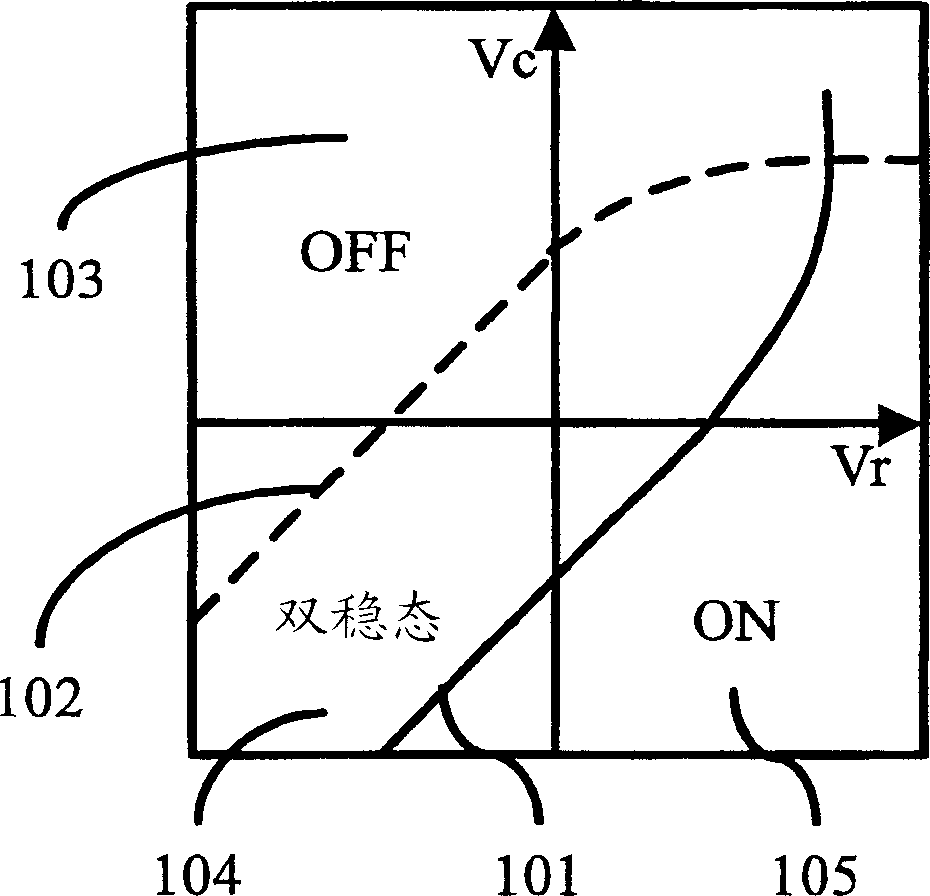
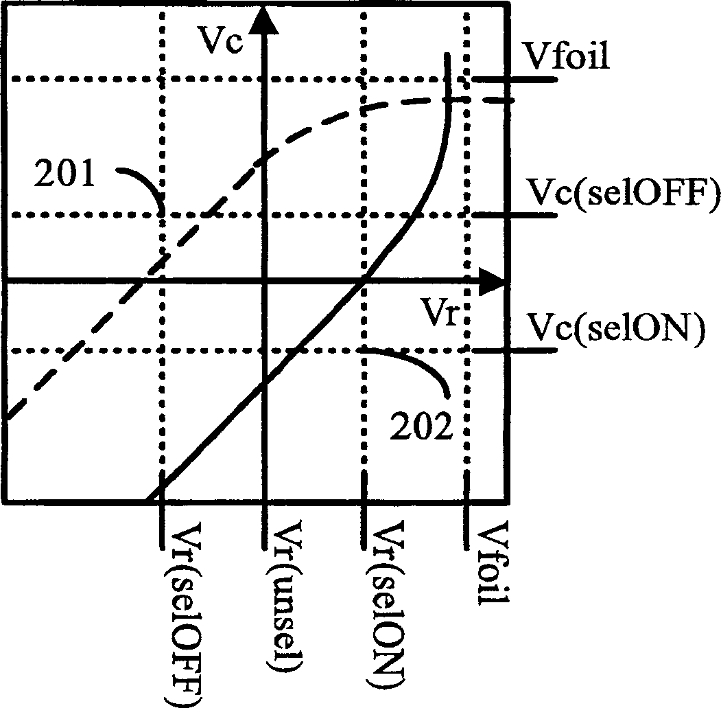
[0043] The driving of dynamic foil displays relies on bistability and hysteresis. A pixel is addressed by voltages applied to row and column electrodes associated with the pixel. The voltage applied to the electrodes can be divided into three distinct regions, the ON region where the pixel is in its ON state, the OFF region where the pixel is in its OFF-state and the intermediate bistable region where the pixel remains in its current state. figure 1 Schematic representation of the relevant voltages that can be applied to a pixel. The x-axis corresponds to the row electrod...


PUM


Abstract

The present invention relates to the driving of optical displays, such as Dynamic Foil Displays, and provides dynamic adaptation of the number of subfields into which frame times of such displays are divided. The number (1202) of subfields can thus be selected depending on for example the ambient light conditions (1201) and image quality requirement. In particular, a smaller number of subfields facilitates brighter images, whereas a larger number of subfields facilitates an increased number of gray scales and/or motion artifact reduction.

Description

technical field [0001] The present invention relates to an optical display, such as a dynamic foil display, and in particular to driving such a display using subfields. Background technique [0002] An optical display is a display in which each pixel independently modulates light from a light source such as a backlight, front light, illumination light, or light guide to produce an image. [0003] A dynamic foil display (Dynamic Foil Display, DFD) generally includes a display panel with a light guide plate used as an active plate, a passive plate, and an active foil sandwiched between the two plates, as well as a selection device. The movable foil is provided with transparent electrodes to which a foil voltage can be applied. The pixels are usually arranged in a matrix structure, and each pixel is located at the intersection of the horizontal scanning electrodes on the passive board and the vertical address electrodes on the active board. Depending on the voltage settings b...

Claims


Application Information

Patent Timeline
Patent Type & Authority Applications(China)
IPC IPC(8): G09G3/20G09G3/34G09G3/00
CPCG09G3/2022G09G3/3433G09G2340/0428G09G2320/0626G09G2320/10G09G2360/144G09G2320/0261
Inventor R·范沃登伯格
Owner KONINKLIJKE PHILIPS ELECTRONICS NV
Why Eureka
Try Eureka