Controllable glide energy-saving damping body of motorcycle
A cushioning body and motorcycle technology, which is applied to vehicle parts, vehicle gearboxes, transportation and packaging, etc., can solve the problems of unreplaceable sprockets, increased exhaust pollution, worn parts, etc., to facilitate replacement, and the control mechanism is simple and reliable , good interchangeability
- Summary
- Abstract
- Description
- Claims
- Application Information
AI Technical Summary
Problems solved by technology
Method used
Image

Examples
specific Embodiment approach 1
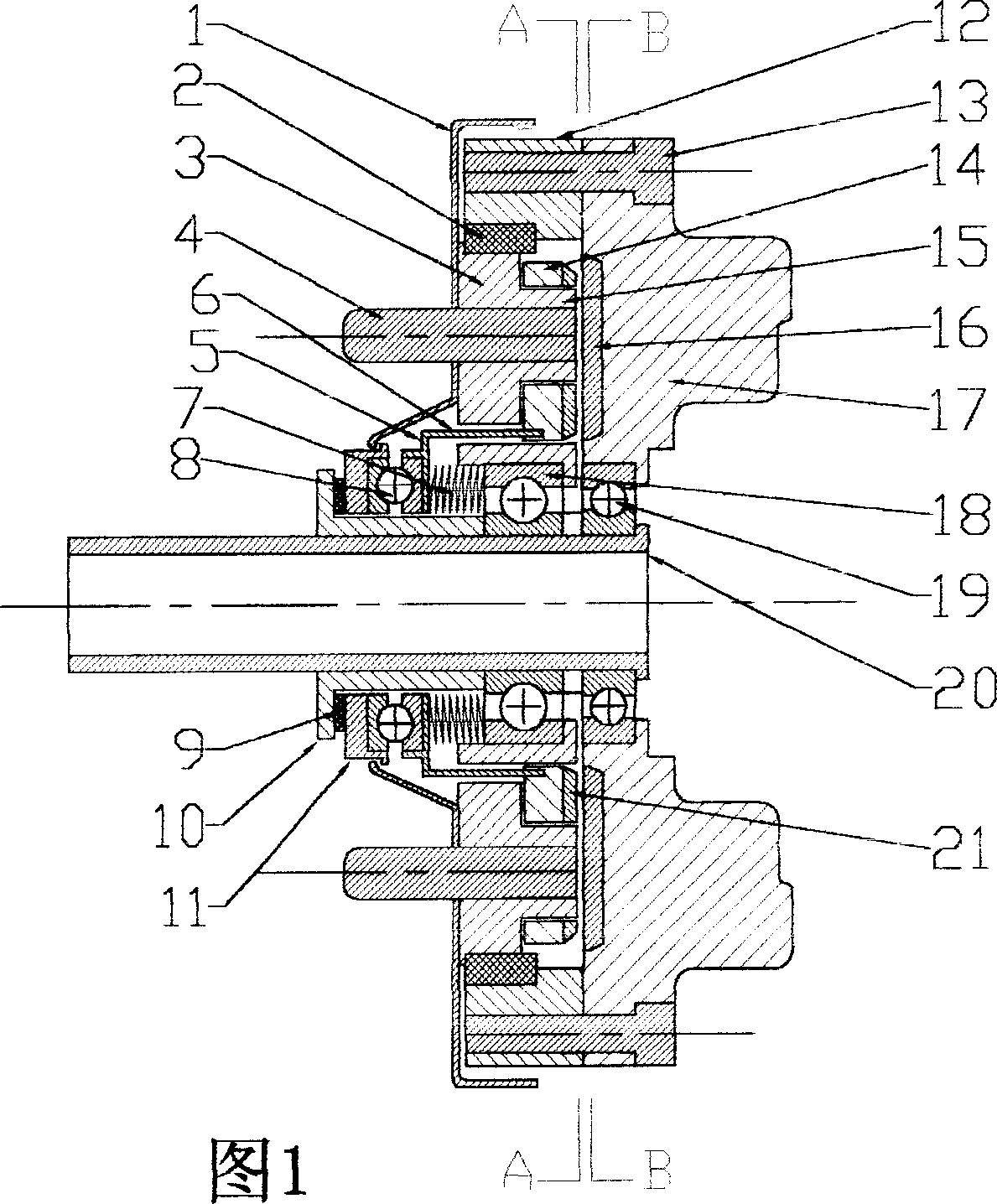
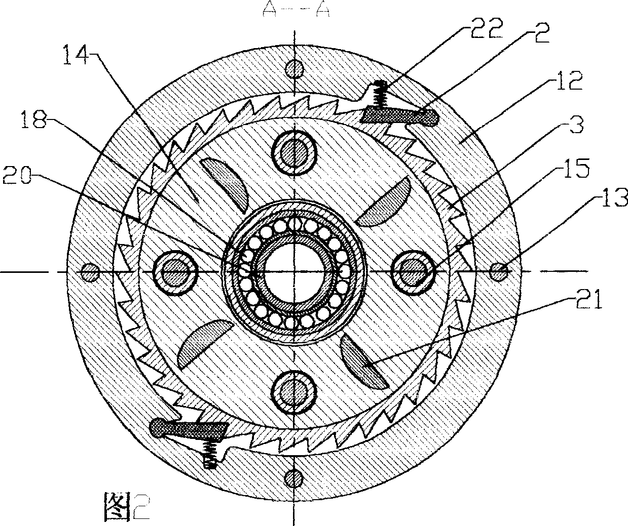
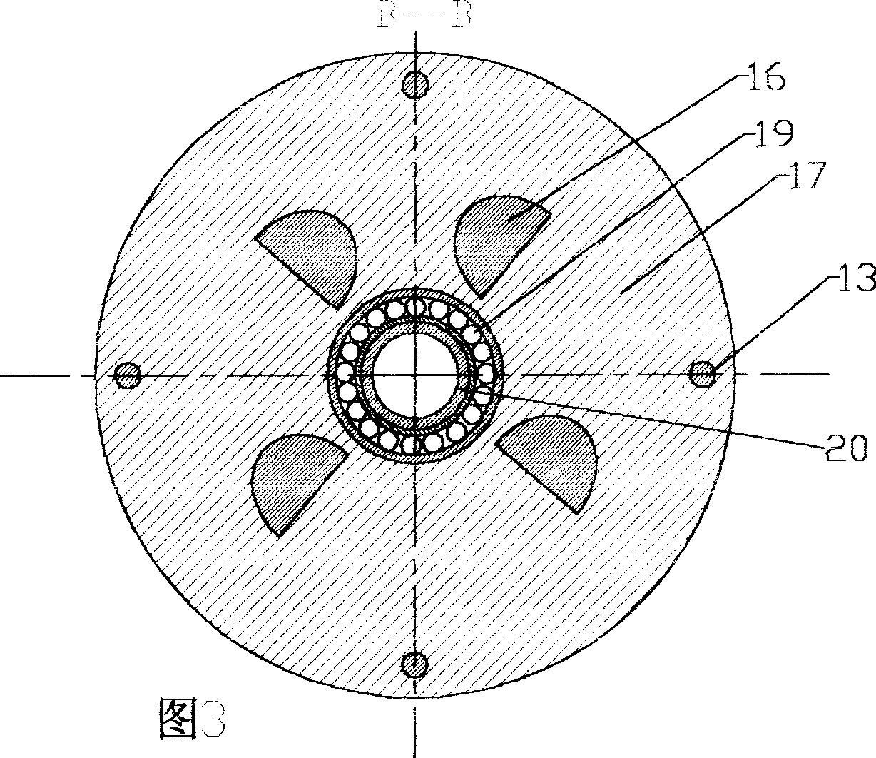
[0028]Specific embodiment one: see Fig. 1, Fig. 2, Fig. 3, utilize one-way overrunning slide assembly and control the protruding tooth (21) on the locking wheel (14) and the concave tooth (16) inside power take-off wheel (17) Engage or disengage control coasting. One side of the inner ring (3) of the one-way overrunning slide assembly is provided with a sprocket installation screw (4) and a dust cover (1), the center of the circle is provided with a bearing (18), and the other side is provided with a sprocket installation screw The concentric boss (15), the locking wheel is sleeved on the boss through symmetrically arranged holes, and the ejector rod (6) connected to the pull plate (5) on one side is solidly integrated and the other side is provided with convex teeth. The outer ring (12) of the overrunning slide assembly is integrated with the power take-off wheel through a screw (13), the inner side of the power take-off wheel is provided with concave teeth, the center of the...
specific Embodiment approach 2
[0029] Specific embodiment two: see Fig. 5, Fig. 6, Fig. 7, utilize one-way overrunning slide component and ratchet (31) to be arranged on inner ring B (28), inner ratchet is arranged on the reverse of outer ring B (24) structure The directional one-way overrunning sliding component controls the sliding by controlling the engagement or disengagement of the pawl and the inner ratchet. The inner ring A (27) and the inner ring B of the two overrunning sliding components are connected with the dust cover (1) through the sprocket installation screw (4), the center of the inner ring is provided with a bearing (18), and the outer ring A (23 ) and the outer ring B are integrated with the power take-off wheel (17) through the screw (13), the center of the power take-off wheel is provided with a bearing (19), and the inner rings of the two bearings are sleeved on the rear wheel bushing (20) and The axial transmission control assembly is matched, wherein the pawl in the one-way overrunni...
specific Embodiment approach 3
[0030] Specific implementation mode three: see Fig. 8 and Fig. 9 , the sliding is controlled by using the one-way overrunning sliding assembly and the opposite direction pawl which is meshed together on the same gear. One side of the outer ring C (32) is provided with a sprocket installation screw (4) and a dust cover (1), and its outer ring is connected to the outer ring of the power output wheel (17) through a bearing (33). The inner ring is provided with two sets of pawls in opposite directions. The inner ring C (35) of the power take-off wheel is a gear structure. Under the action of small springs, the inner ring C is engaged with each other. The center of the inner ring C is provided with a bearing (34). 36) is provided with a tapered ejector rod (37) connected to the pull plate (5) to control the engagement or disengagement of the ratchet with the inner ring C gear. When the claw (9) does not apply axial thrust, the pull plate Under the action of the inner spring (7), t...
PUM
 Abstract
Description
Claims
Application Information
 - R&D
- Intellectual Property
- Life Sciences
- Materials
- Tech Scout
- Unparalleled Data Quality
- Higher Quality Content
- 60% Fewer Hallucinations
Browse by: Latest US Patents, China's latest patents, Technical Efficacy Thesaurus, Application Domain, Technology Topic, Popular Technical Reports.
© 2025 PatSnap. All rights reserved.Legal|Privacy policy|Modern Slavery Act Transparency Statement|Sitemap|About US| Contact US: help@patsnap.com