Apparatus and method for detecting electronic declination angle of communication antenna

A communication antenna and detection device technology, which is applied in the direction of measuring devices, electric devices, antennas, etc., can solve the problems of not meeting the stepping standard and complex structure, and achieve the effect of simple structure, avoiding fatigue, and avoiding the trouble of climbing stairs

Inactive Publication Date: 2006-02-15
GCI SCI & TECH
View PDF1 Cites 23 Cited by
  • Summary
  • Abstract
  • Description
  • Claims
  • Application Information

AI Technical Summary

Problems solved by technology

Argus's electronically adjustable antenna is closed-loop control, using separate resistors to line up, the structure is mor

Method used


Image

  • Apparatus and method for detecting electronic declination angle of communication antenna
  • Apparatus and method for detecting electronic declination angle of communication antenna

Examples


Embodiment Construction

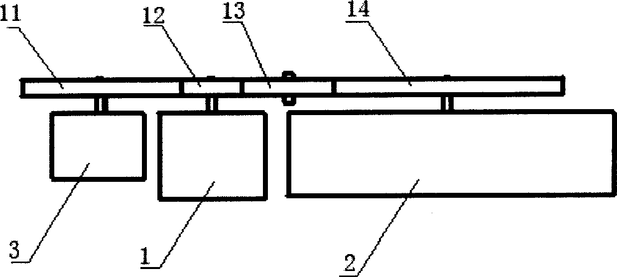
[0028] Such as figure 1 As shown, a detection device for the electrical downtilt angle of a communication antenna uses a rotary potentiometer, the motor drive device 1 is a drive motor containing a reducer, the potentiometer 3 is a rotary potentiometer, and the The gear 12 on the rotating shaft of the driving motor is coupled with the gear 14 mounted on the rotating shaft of the phase shifter 2 through the intermediate gear 13, and the gear 12 on the rotating shaft of the driving motor is simultaneously connected with the rotating shaft of the rotary potentiometer. Gear 11 meshes.

[0029] The driving motor including the reducer drives the gear 12 to rotate; the gear 12 is coupled through the intermediate gear 13 to drive the gear 14; and the gear 14 drives the phase shifter 2 to rotate. The gear 12 drives the potentiometer 3 to rotate through the gear 11 at the same time. When designing the transmission system, pay attention to make the full movement time of the phase shift...


PUM


Abstract

This invention relates to a device and method of detecting the angle of communication antenna downdiping, which comprises the following parts: motor driver (1), phase shifter (2), potentiometer (3). The moving end of potentiometer (3) connects the mobile portion of phase shifter (2) mechanically. The motor driver (1) synchronizes the motion of the phase shifter (2) and potentiometer (3).

Description

Technical field [0001] The invention relates to a detection device for the electric downtilt angle of the electric adjustment antenna of a mobile communication base station, and also relates to a detection method using the detection device for the electric downtilt angle of the communication antenna. Background technique [0002] Plate-shaped base station antennas are widely used in the field of mobile communications, and the downtilt angle of the antenna determines the coverage area that the antenna beam points to. Antennas that use mechanical angle adjustment or fixed electrical downtilt have been difficult to meet the requirements of network optimization. The electronically adjustable antenna is very suitable for solving the problem of cross-area interference caused by dense users and small station distance in large and medium-sized cities, and it is very convenient to solve the problem of temporary traffic hotspots that often appear in urban areas. In communication netw...

Claims


Application Information

Patent Timeline
IPC IPC(8): G01B7/30H01Q3/30
Inventor 陈龙潭
Owner GCI SCI & TECH
Why Eureka
Try Eureka