Multidimensional adjustable optical image moving device

A multi-dimensional, phase-shifting technology, applied in the field of optical phase, to achieve the effect of high precision, fast mechanical response, simple and compact structure

Inactive Publication Date: 2006-02-22
SHANGHAI INST OF OPTICS & FINE MECHANICS CHINESE ACAD OF SCI
View PDF0 Cites 20 Cited by
  • Summary
  • Abstract
  • Description
  • Claims
  • Application Information

AI Technical Summary

Problems solved by technology

Obviously, the above-mentioned single adjustable degr

Method used


Image

  • Multidimensional adjustable optical image moving device
  • Multidimensional adjustable optical image moving device
  • Multidimensional adjustable optical image moving device

Examples


Embodiment Construction

[0017] The structure and working principle of the present invention will be further described below in conjunction with the accompanying drawings.

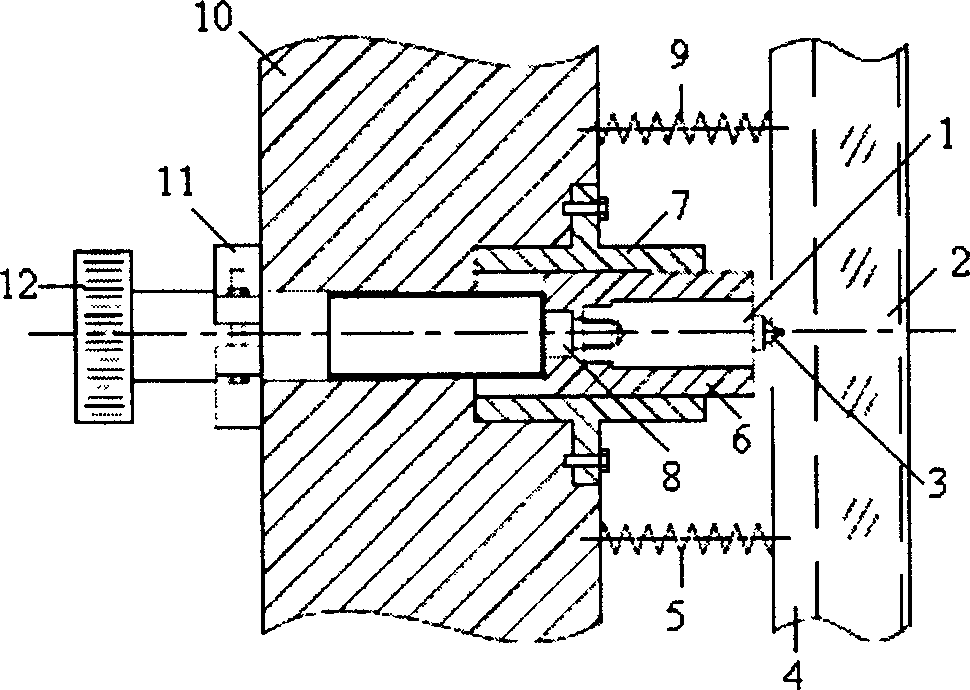
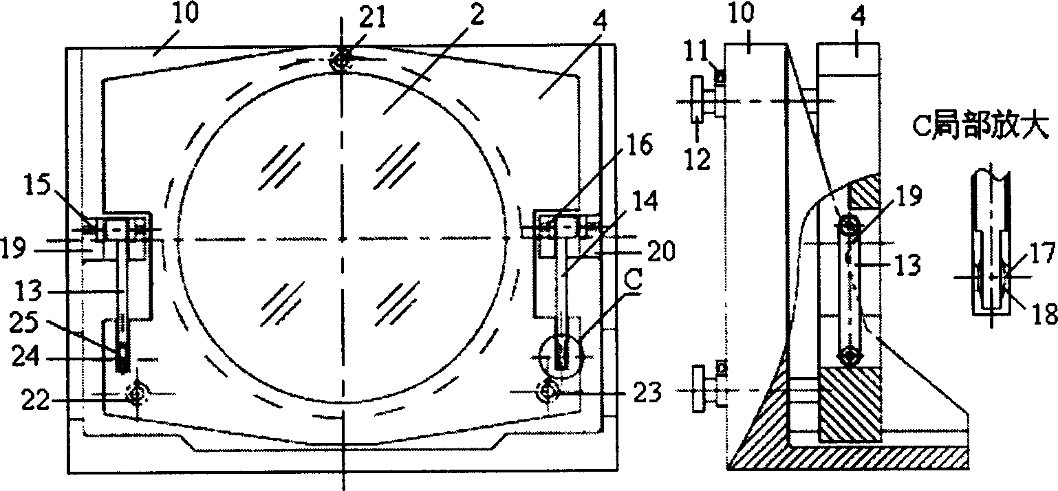
[0018] see first figure 2 and image 3 , figure 2 It is a structural schematic diagram of the optical phase shifting device of the multi-dimensional adjustable optical phase shifting device of the present invention, image 3 It is a structural schematic diagram of the multidimensional adjustable optical phase shifting device of the present invention, as can be seen from the figure, the multidimensional adjustable optical phase shifting device of the present invention includes a base 10 and a mirror holder 4, and is opposite between the base 10 and the mirror holder 4. Three phase-shift adjustment devices 21 , 22 , 23 with the same structure arranged in a triangle on the base 10 and two cantilever structures distributed symmetrically on the left and right, and the reference mirror 2 placed in the mirror holder 4 .

[0019] The...


PUM


Abstract

This invention relates to one optical displacement device to realize multi-dimension adjusting controlled by machine, which comprises base socket, lens socket, referent lens inside, hanging arm, acting joint axis and the three same displacement device, wherein, each displacement device is composed of screw area, locking structure and piezoelectricity ceramics; the ceramics is fixed on the case with one end contact to the v shape groove of the lens socket and steel ball; the case can slide inside the groove; the screw bar is located with locking structure on the base socket.

Description

technical field [0001] The invention relates to an optical phase, and is a multi-dimensional adjustable optical phase shifting device, in particular an optical phase shifting device with multi-dimensional coarse adjustment and fine adjustment. Background technique [0002] Since the 1970s, the phase-shifting interferometry technology has been greatly developed, and has been widely used in various modern interferometers with its excellent test accuracy, and has become an effective method for optical high-precision metrology testing. The phase-shifting device is the main part of the phase-shifting interferometer, and the phase of the wave front is changed through its displacement change, and the displacement adjustment error is one of the main factors affecting the accuracy of the interferometer's wavefront restoration. Piezoelectric ceramics (electrostrictive micro-displacers) are widely used in phase-shifting interference devices because of their high micro-displacement prec...

Claims


Application Information

Patent Timeline
IPC IPC(8): G01B9/02G02B26/06G02B26/08G02B27/60
Inventor 李安虎刘立人栾竹
Owner SHANGHAI INST OF OPTICS & FINE MECHANICS CHINESE ACAD OF SCI
Why Eureka
Try Eureka