Handheld type electric tool machine

An electric tool and hand-operated technology, applied in the field of hand-operated electric tool machines, can solve the problem of high installation cost

Inactive Publication Date: 2006-02-22
ROBERT BOSCH GMBH
View PDF0 Cites 0 Cited by
  • Summary
  • Abstract
  • Description
  • Claims
  • Application Information

AI Technical Summary

Problems solved by technology

If it is necessary to change the structure and assembly proc

Method used


Image

  • Handheld type electric tool machine
  • Handheld type electric tool machine
  • Handheld type electric tool machine

Examples


Embodiment Construction

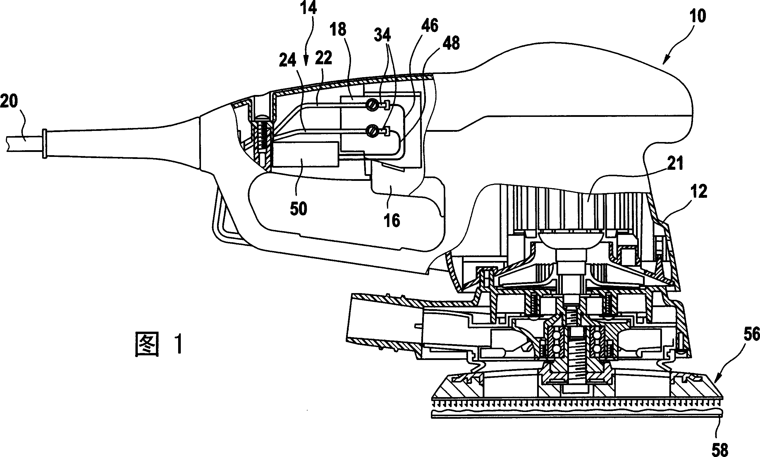
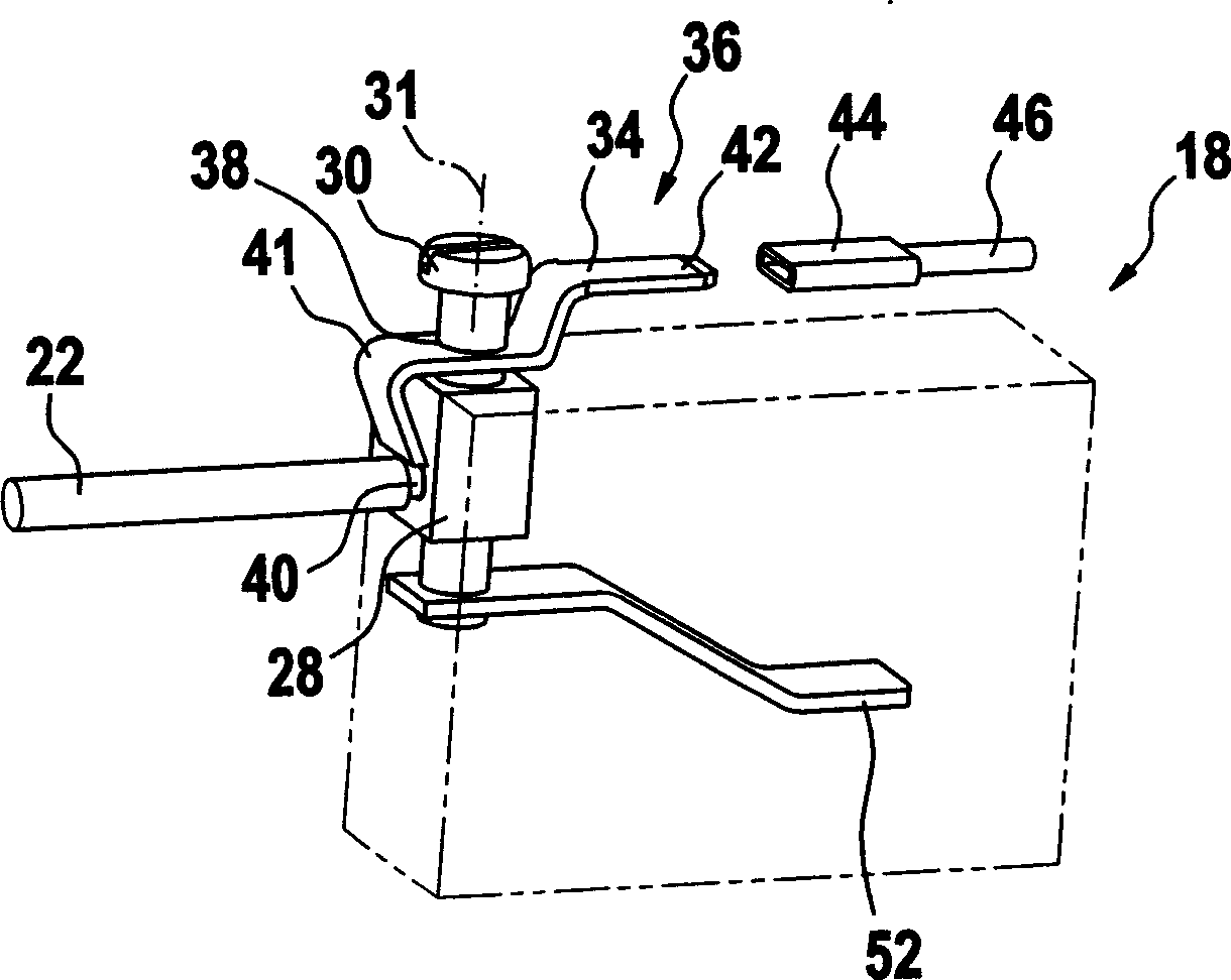
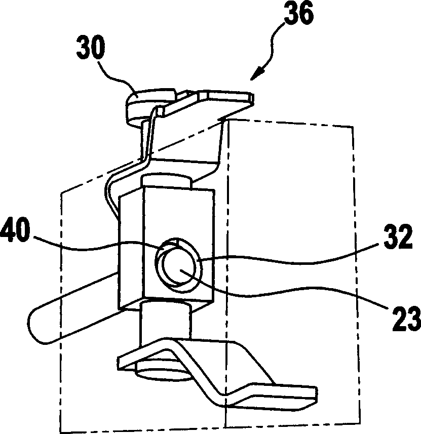
[0020] FIG. 1 shows a partially cutaway side view of a hand-operated power tool 10 designed as an eccentric grinder. The hand-operated power tool has a housing 12 with a handle 14 at the upper left in the viewing direction, in which an upwardly movable switch key 16 is arranged for operating an electric switch 18 . A power supply cable 20 leads to the switch 18 , which cable—to the left in the viewing direction—leads out of the handle 14 at the rear. The power supply cable 20 contains two electrical conductors 22 , 24 , whose ends are fastened to the switch 18 by means of an electrical connection 26 so that they can make electrical contact with the switch 18 . The electrical connection 26 is designed as a contact block 28 which is provided with a threaded hole 27 into which a clamping screw 30 is screwed. Furthermore, the contact block 28 is provided with a hole 32 perpendicular to and intersecting the longitudinal axis 31 of the screw 30 ( figure 2 , 3).

[0021] The elec...


PUM


Abstract

The invention relates to a manually-operated electric tool which comprises a switch (18) for switching on or switching off the circuit of an electric driver (21) thereof, and electric connection devices (26, 28) arranged in the circuit. The manually-operated electric tool can be easily modified by adding circuits to meet the corresponding newly requirements for safety. The manually-operated electric tool further comprises a coupling device (36) used for subsequent electrical connections of the circuit, particularly electrical connection with electric and/or electronic circuits (50) that are not originally provided in the power circuit.

Description

technical field [0001] The invention relates to a hand-operated electric power tool with a switch for switching on and off the circuit of its electric drive and with electrical connections for electrical lines arranged in the circuit. Background technique [0002] Various, in particular mains-operated, hand-held electric power tools are already known, which are substantially modified since they must comply with future safety regulations and must have a restart preventer, for example starting from a certain power level. If the structure and the assembly process have to be changed for this purpose, its subsequent installation costs are high. Contents of the invention [0003] According to the invention, a hand-operated electric power tool is proposed with a switch for switching on and off the circuit of its electric drive and with electrical connections arranged in the circuit for electrical leads, wherein , which has a coupling device for a subsequent electrical connection...

Claims


Application Information

Patent Timeline
IPC IPC(8): H02K11/00B25D11/00H01R4/36H02K5/22H02K23/66
CPCH01R4/363H01R13/04
Inventor 恩斯特・克伦兹勒米夏埃多・哈贝勒尤斯图斯・兰普雷希特乌尔里希・辛格
Owner ROBERT BOSCH GMBH
Why Eureka
Try Eureka