
Voxel-driven spiral reconstruction for cone-beam computer tomography

A technology of voxel, tomography, applied in computing, generation of 2D images, instruments for radiological diagnosis, etc., can solve the problems of complexity, inflexibility, etc.

Inactive Publication Date: 2006-03-01
SIEMENS AG
View PDF0 Cites 11 Cited by
  • Summary
  • Abstract
  • Description
  • Claims
  • Application Information

AI Technical Summary

Problems solved by technology

The exact reconstruction algorithm should be avoided due to its complexity and inflexibility

Method used


Image

  • Voxel-driven spiral reconstruction for cone-beam computer tomography
  • Voxel-driven spiral reconstruction for cone-beam computer tomography
  • Voxel-driven spiral reconstruction for cone-beam computer tomography

Examples


Embodiment Construction

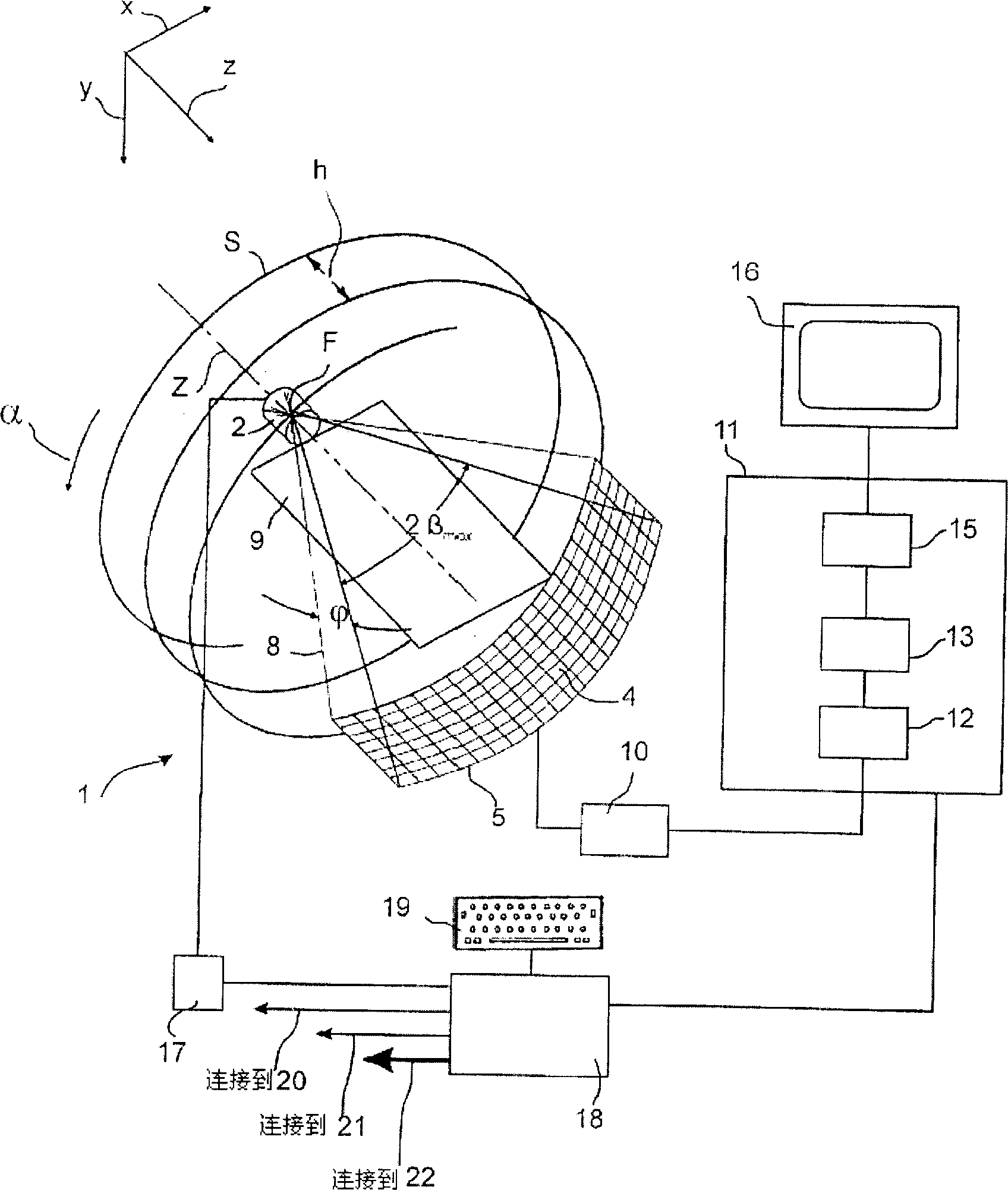
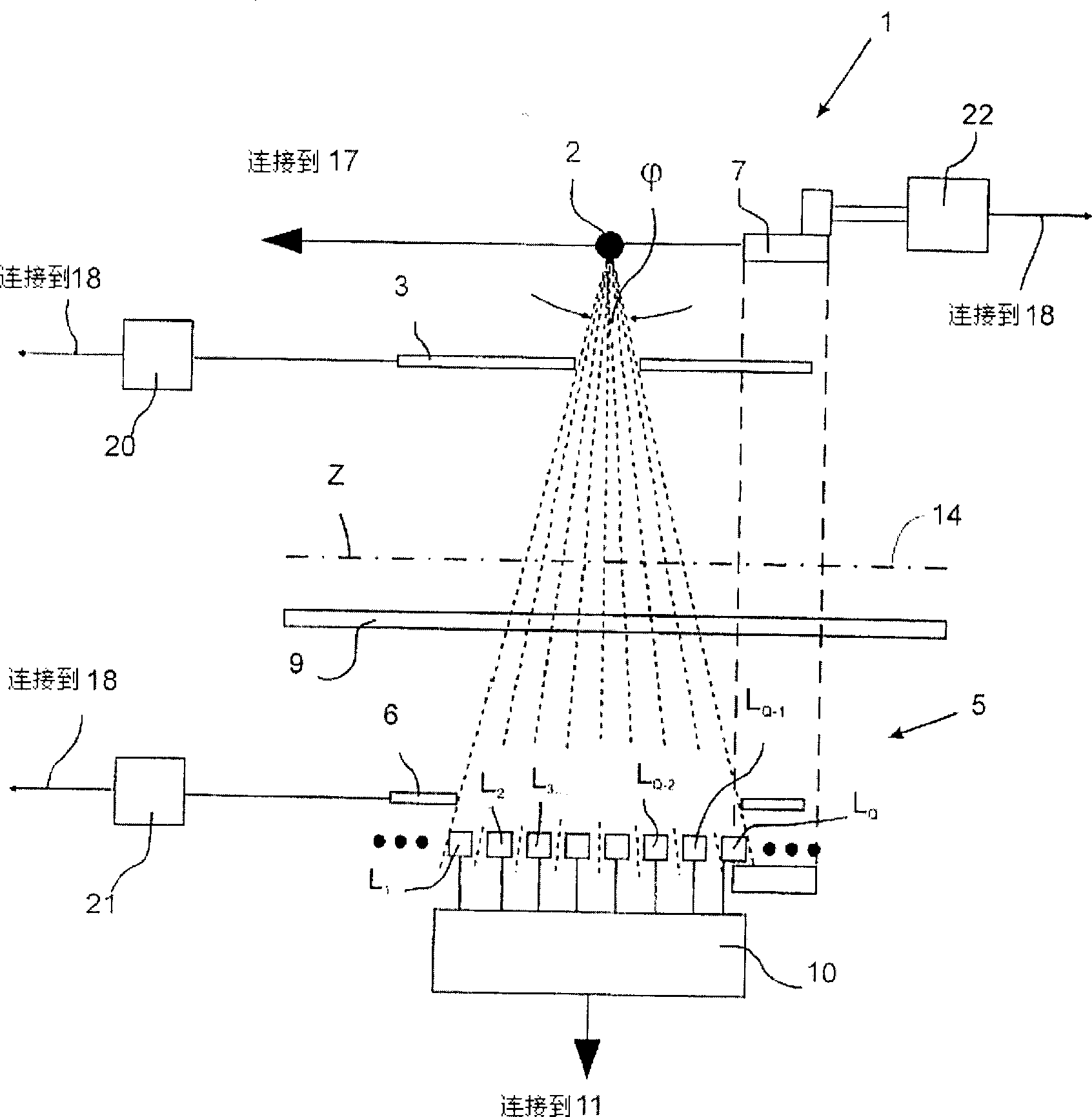
[0036] figure 1 and figure 2 A partial perspective view of a third generation multi-array CT unit suitable for carrying out the methods involved in the present invention is shown. The measuring device 1 (ie, the rack) contains an X-ray source 2, and a ray aperture 3 close to the light source is arranged at its front end. The detection receiver 5 is composed of a two-dimensional structural array including multiple rows and columns of scanning units, such as figure 2 As shown in the sectional view of the detector receiver 5, a ray aperture 6 near the detector is provided at the front end. For clarity, figure 1 Only shown from L 1 to L Q The eight-row scanning unit 4. The detection receiver 5 can either have a larger number of rows or a different planar configuration for the detection device without departing from the scope of the invention.

[0037] One end made up of X-ray source 2 and ray aperture 3 and the other end made up of detection receiver 5 and ray aperture ...


PUM


Abstract

A method is disclosed for generating computer tomography images using a 3D image reconstruction method. According to the method, to scan an object to be examined using a cone-shaped bundle of rays originating from a focal point and a planar, preferably multi-line detector for detecting the bundle of rays, the focal point is displaced along a spiral trajectory around the object to be examined. The detector delivers output data corresponding to the detected radiation and image voxels from the scanned examined object are reconstructed from the optionally pre-processed output data, the image voxels reflecting the attenuation coefficients of the respective voxel. Each image voxel is reconstructed separately from projection data, which covers a projection angular range of at least 108° and an approximate weighting is carried out for each voxel considered in order to standardize the projection data using the voxel.

Description

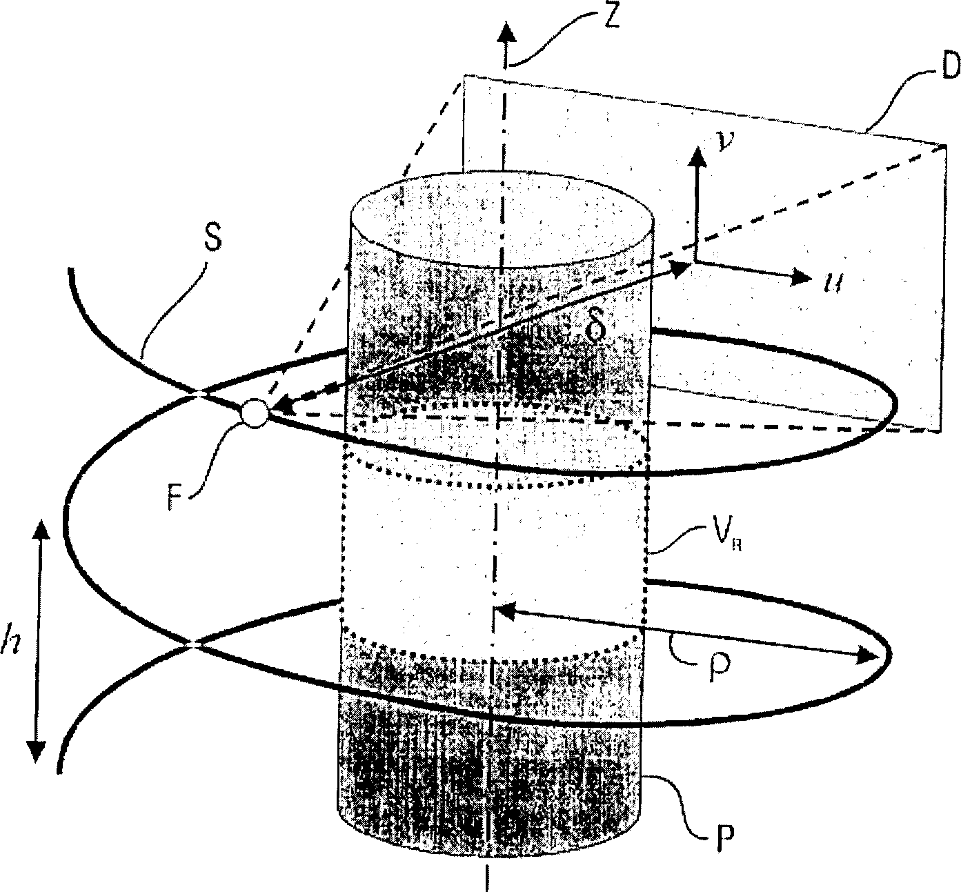
technical field [0001] The invention relates to a method for generating computed tomography (CT) images by using a 3D image reconstruction method. According to the method, an object to be inspected is scanned by using a cone beam emitted from a focal point and a planar, preferably multi-array, detector for detecting the cone beam. During the detection process, the focal point will move on a spiral trajectory around the object to be inspected. At the same time, the detector provides output data corresponding to the detected rays, and the image voxels of the detected object will be selected from the pre-processed is reconstructed in the output data, and the image voxels replicate the attenuation coefficients of each voxel. Background technique [0002] Existing CT imaging techniques relying on multi-array detectors use cone geometry beams. When reconstructing an image volume, the influence of cone ray geometry must be taken into account in the generated 3D image, which makes...

Claims


Application Information

Patent Timeline
Patent Type & Authority Applications(China)
IPC IPC(8): G06T11/00
CPCA61B6/027G06T11/006
Inventor 赫伯特·布鲁德冈特·劳里奇卡尔·斯蒂尔斯托弗
Owner SIEMENS AG
Learn More