Button cell

A button battery and battery casing technology, which is applied to battery components, circuits, electrical components, etc., can solve the problems of reducing the negative electrode casing, reducing the sealing performance, and reducing the battery capacity, so as to prevent leakage and prevent battery capacity. The effect of reducing and inhibiting plastic deformation

Active Publication Date: 2006-03-08
MAXELL HLDG LTD
View PDF6 Cites 18 Cited by
  • Summary
  • Abstract
  • Description
  • Claims
  • Application Information

AI Technical Summary

Problems solved by technology

[0010] But the problem is that the outer peripheral side wall of the negative electrode case is pressed to the inner side of the battery by the chiseling force and the outer peripheral side wall is deformed toward the inner side of the battery, which reduces the sealing performance, so that there is a possibility of liquid leakage from the sealing part
And, because the internal volume of the battery is reduced, the deformation part of the outer peripheral side wall of the negative electrode casing is reduced, thereby reducing the battery capacity

Method used


Image

  • Button cell
  • Button cell
  • Button cell

Examples


Embodiment 1

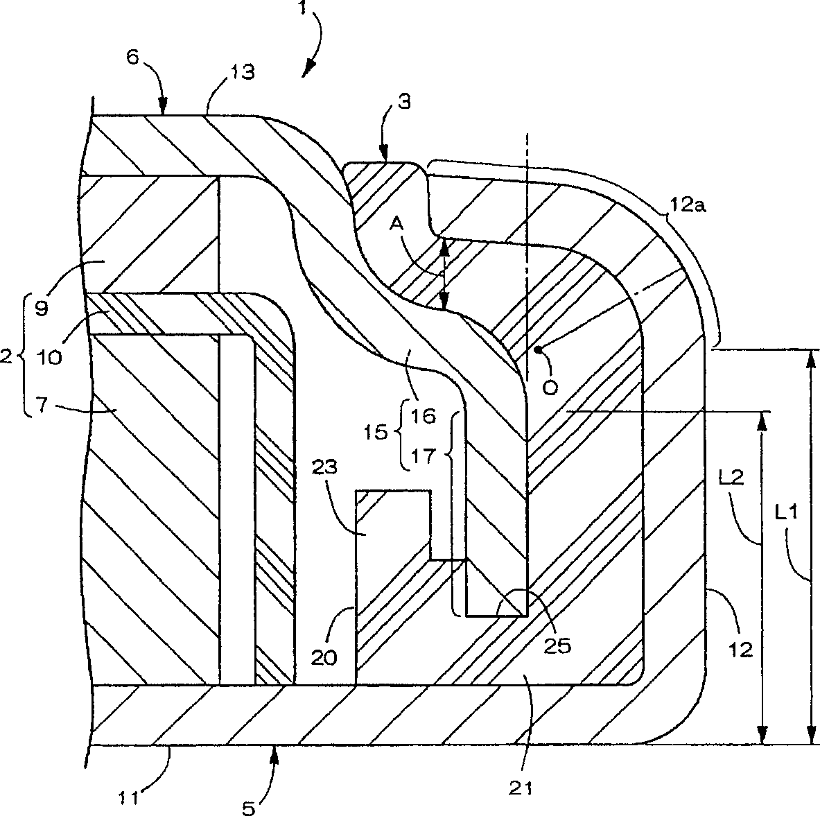
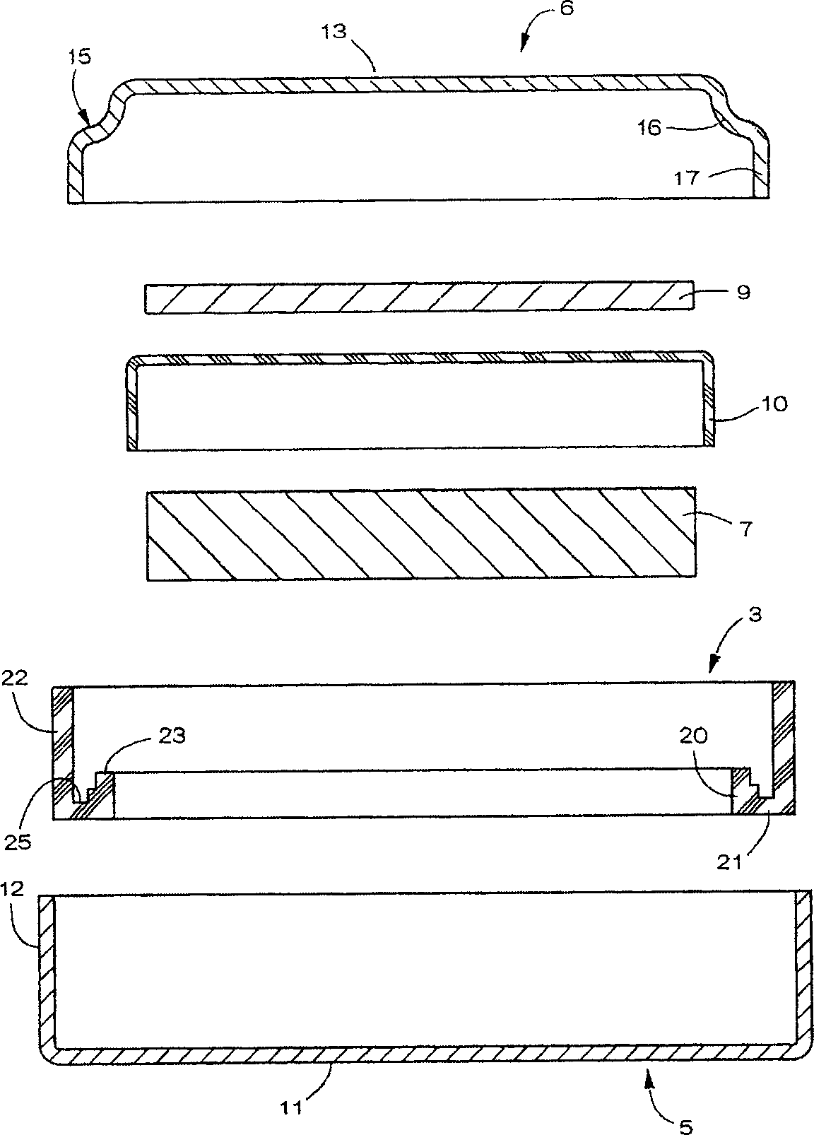
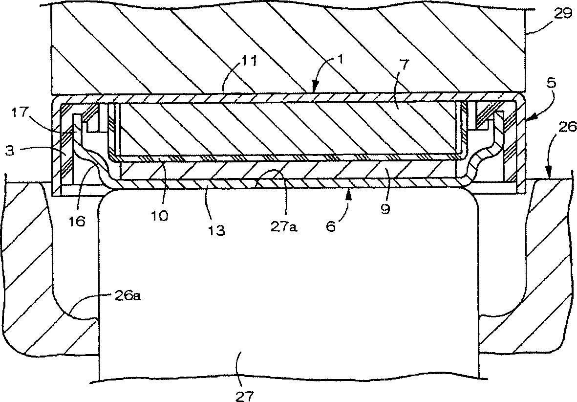
[0031] figure 1 and figure 2 Example 1 showing a button-type battery as the object of the present invention, such as figure 1 As shown, the battery case 1 has: a power generating element 2 accommodated in the battery case 1, a sealing gasket 3 sealed inside the battery case 1, and a positive electrode case 5, which are fastened and fixed on the inner edge of the opening of the positive electrode case 5 through the sealing gasket 3 The negative electrode casing 6 is formed into a flat button shape as a whole. Incidentally, the outer diameter dimension of the battery case 1 is 12 mm, and the upper and lower thickness dimensions are 2 mm.

[0032] The power generating element 2 includes a positive electrode material 7 and a negative electrode material 9 solidified in a disk shape, and a separator 10 installed therebetween. The main component of the positive electrode material 7 is manganese dioxide, and the negative electrode material 9 is composed of metal lithium. The sepa...

Embodiment 2

[0044] In Example 2, the radius of curvature of the curved portion 12 a of the outer peripheral cylindrical wall 12 of the positive electrode case 5 was set to 0.8 mm. The direction A in which the sealing gasket 3 is most compressed is inclined at 84 degrees with respect to the bottom wall 11 of the positive electrode case 5 . Since the others are the same as those in Embodiment 1, description thereof will be omitted.

Embodiment 3

[0046] In Example 3, the inward front end of the curved portion 12 a of the outer peripheral cylindrical wall 12 of the positive electrode case 5 is closer to the outside of the battery than the inner peripheral surface of the straight portion 17 of the negative electrode case 6 . Since other points are the same as in Embodiment 1, description thereof will be omitted.


PUM

PropertyMeasurementUnit
sizeaaaaaaaaaa

Abstract

To obtain a coin-shaped cell, in which liquid leakage from a sealed part can be prevented surely, while reduction of cell capacity is suppressed. A cell can for housing a power generation element includes a cathode can of which an outer peripheral cylindrical wall is bent upward from the outer peripheral brim of a bottom face wall, and an anode can of which an outer peripheral side wall is bent downward from the outer peripheral brim of an upper face wall. An upper end peripheral brim part of the peripheral cylindrical wall of the cathode can is calking worked inward via a gasket mounted on the outer peripheral side wall of the anode can. The outer peripheral side wall of the anode can includes an enlarged diameter part thrusting in a step form an an angle downward from the outer peripheral brim of the upper face wall, and a straight part linearly extending downward continually to the enlarged diameter part, so that the center of the curvature of a curving part of the outer peripheralcylindrical wall that is bent inward by the calking work of the outer peripheral cylindrical wall of the anode can is made to be positioned at further outside than the outer peripheral side wall of the anode can.

Description

technical field [0001] The present invention relates to a button cell, which comprises a positive electrode case that bends the outer peripheral cylinder wall upward from the outer peripheral edge of the circular bottom wall and a negative electrode case that bends the outer peripheral side wall downward from the outer peripheral edge of the circular upper wall, and the positive electrode case The upper end peripheral portion of the outer peripheral cylindrical wall of the positive electrode case is caulked by a gasket mounted on the outer peripheral side wall of the negative electrode case, so that an inwardly bent portion is formed at the upper end of the outer peripheral cylindrical wall of the positive electrode case. Background technique [0002] Such a button battery is disclosed in Patent Documents 1 to 6. Wherein, the shallow disk-shaped negative electrode casing and the shallow disk-shaped positive electrode casing with an outer diameter larger than the negative ele...

Claims


Application Information

Patent Timeline
Patent Type & Authority Applications(China)
IPC IPC(8): H01M2/02
CPCY02E60/10
Inventor 阪本善史山口浩司
Owner MAXELL HLDG LTD
Why Eureka
Try Eureka