

Ultrasonic probe and ultrasonic device
An ultrasonic and probe technology, used in ultrasonic/sonic/infrasonic diagnosis, sonic diagnosis, infrasonic diagnosis, etc., can solve problems such as inconvenience in use, and achieve the effect of improving control accuracy and improving usage.
- Summary
- Abstract
- Description
- Claims
- Application Information
AI Technical Summary
Problems solved by technology
Method used
Image

Examples
no. 1 Embodiment approach
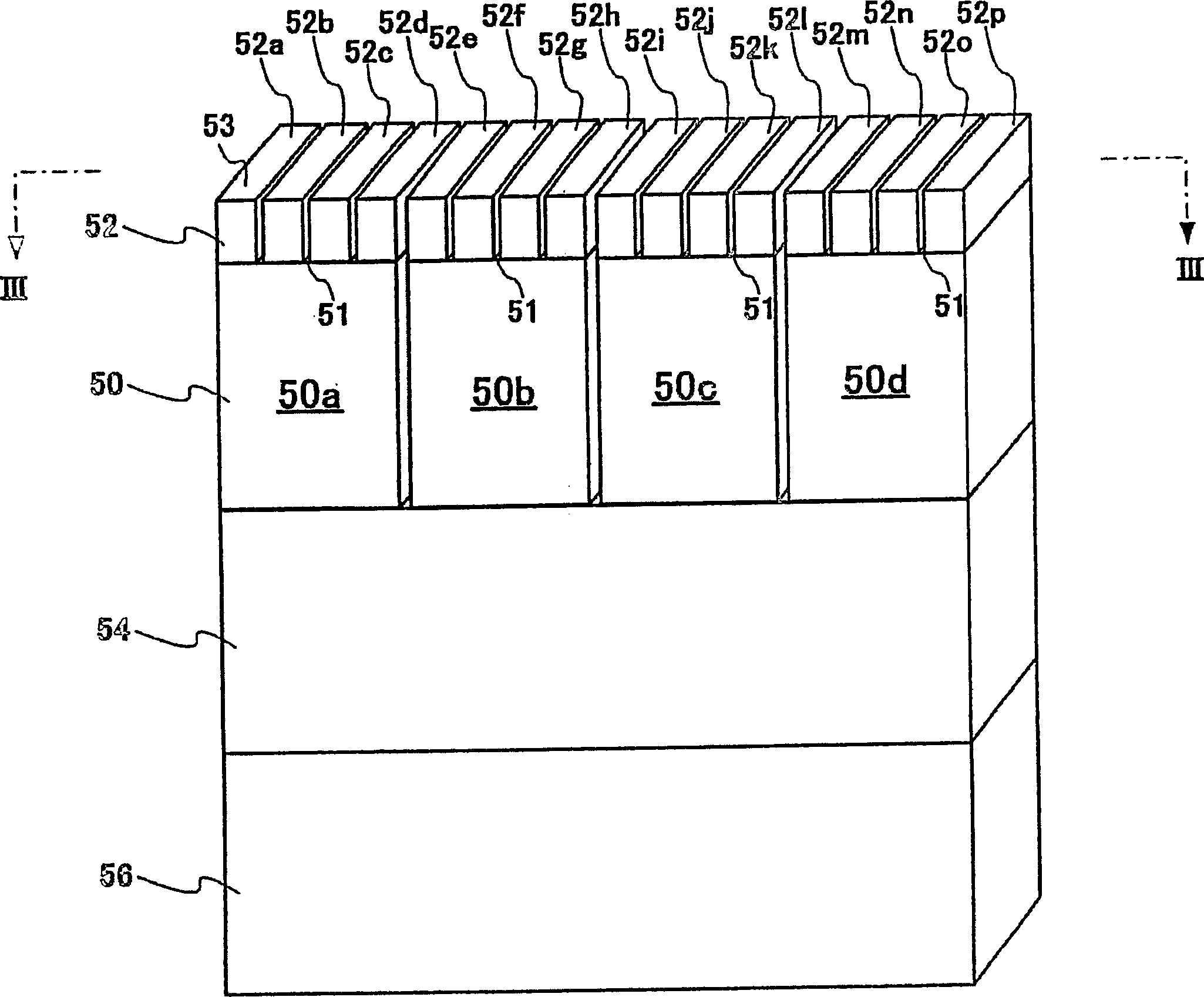
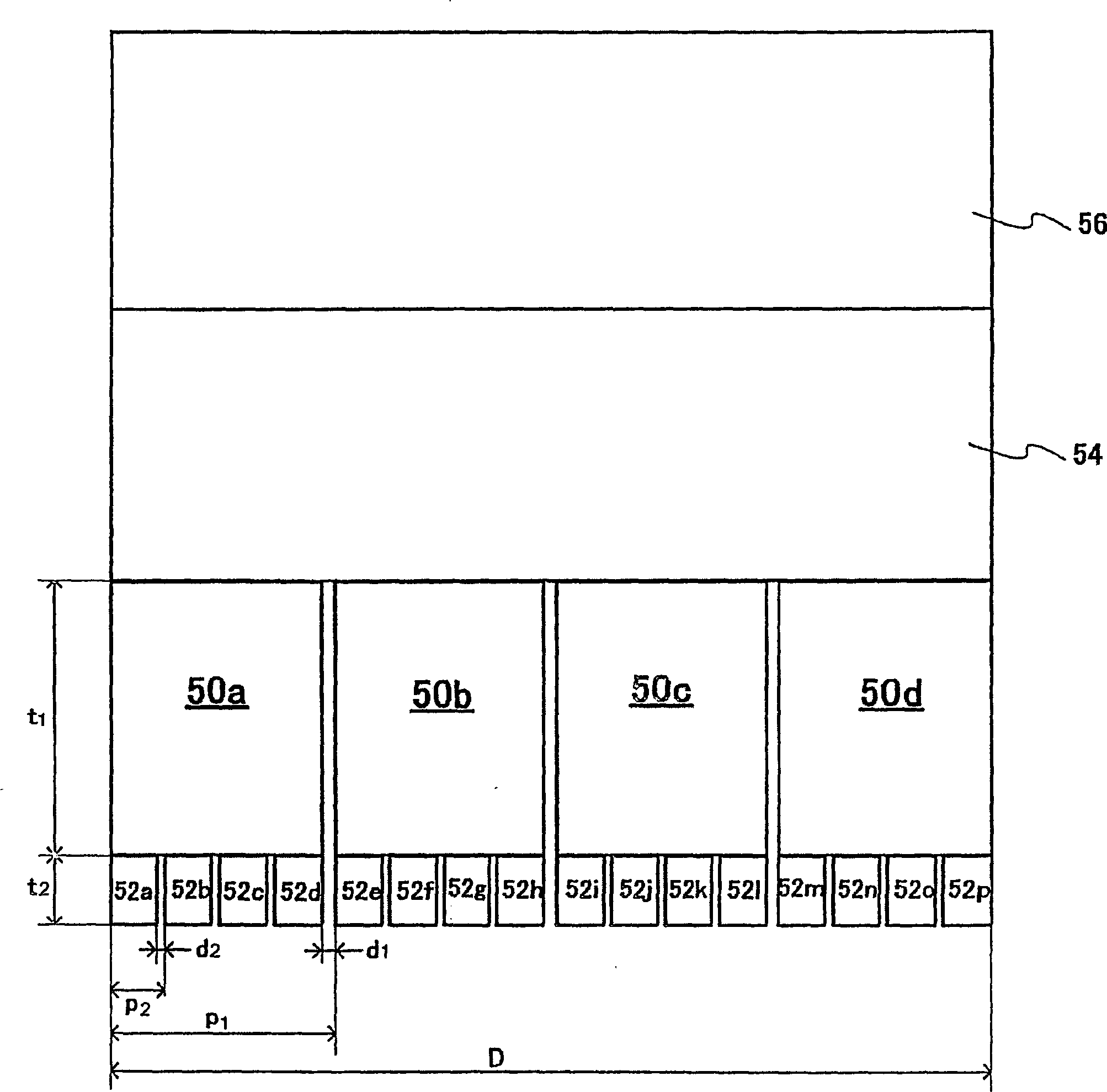
[0025] Next, a first embodiment of an ultrasonic probe and an ultrasonic device to which the present invention is applied will be described. This embodiment is an example of an ultrasonic probe in which a plurality of diagnostic vibrators are stacked on an ultrasonic emitting surface of a therapeutic vibrator.
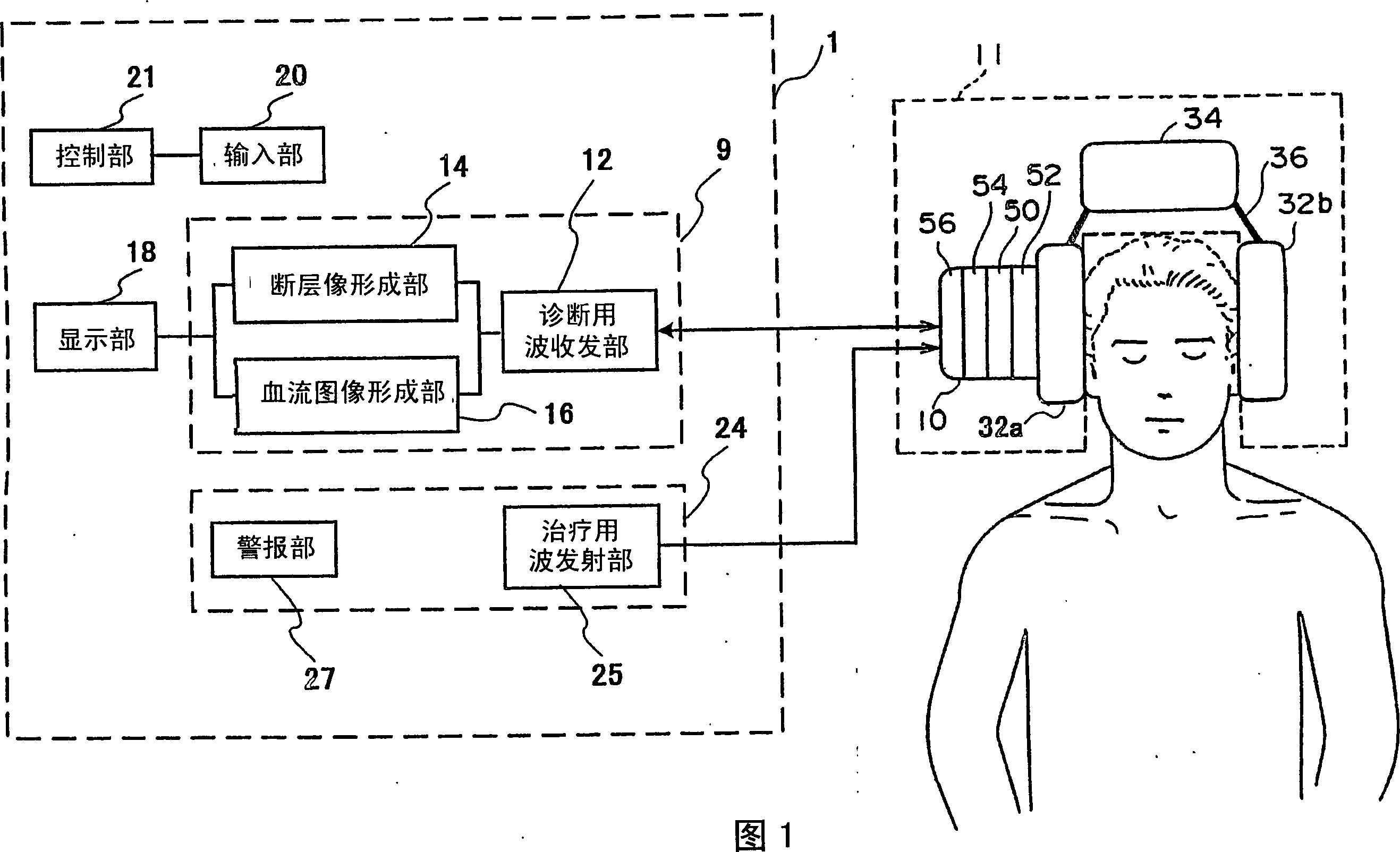
[0026] As shown in FIG. 1 , the ultrasonic device 1 is composed of a diagnostic ultrasonic unit 9 , a therapeutic ultrasonic emitting unit 24 , a display unit 18 , an input unit 20 , a control unit 21 and the like. The diagnostic ultrasonic unit 9 includes: a diagnostic wave transmitting and receiving unit 12 having a diagnostic wave transmitting unit; and an image forming unit including a tomographic image forming unit 14 and a blood flow image forming unit 16 . The therapeutic ultrasonic wave transmitting and receiving unit 24 includes a therapeutic wave transmitting and receiving unit 25, an alarm unit 27, and the like. Furthermore, the diagnostic wave transmitting...
no. 2 Embodiment approach
[0058] For the second embodiment of the ultrasonic probe and ultrasonic device to which the present invention is applied, refer to Figure 6 Be explained. The difference between the present embodiment and the first embodiment is that when blood starts to flow after thrombus is dissolved, the ultrasonic wave for treatment is either stopped or the amplitude of the ultrasonic wave for treatment is reduced. Figure 6 A configuration diagram of an ultrasonic device according to the present embodiment is shown.
[0059] In general, when a thrombus is dissolved by ultrasonic waves for treatment, there is a possibility that ultrasonic waves for treatment may be irradiated even after the blood starts to flow after the thrombus is dissolved. Therefore, in this embodiment, if Figure 6 As shown, a blood flow detection unit 22 is provided. The blood flow detection unit 22 is a component that detects the strength of the Doppler shift signal of the reflected echo signal generated from th...
no. 3 Embodiment approach
[0064] For the third embodiment of the ultrasonic probe and ultrasonic device to which the present invention is applied, refer to Figure 7 Be explained. The difference between this embodiment and the first embodiment is that when the temperature rise of the ultrasonic probe is higher than the set temperature, the frequency and amplitude of the therapeutic ultrasonic waves are reduced or the emission is stopped. Figure 7 A configuration diagram of an ultrasonic device according to the present embodiment is shown.
[0065] In general, when diagnostic and therapeutic ultrasonic waves are emitted from the ultrasonic probe 10 , part of the energy of the emitted ultrasonic waves is converted into heat energy inside the ultrasonic probe 10 . Therefore, there is a possibility that the temperature of the ultrasonic probe 10 may rise. Here, in this embodiment, as Figure 7 As shown, a temperature detection unit 28 is provided. The temperature detection unit 28 detects the temperat...
PUM
 Abstract
Description
Claims
Application Information