Clutch brake

A brake and clutch type technology, applied in the hoisting device and other directions, can solve the problems of unsafety, inconvenient operation, low efficiency, etc., and achieve the effect of strong adaptability and easy operation

Inactive Publication Date: 2006-03-15
李玉芝
View PDF0 Cites 10 Cited by
  • Summary
  • Abstract
  • Description
  • Claims
  • Application Information

AI Technical Summary

Problems solved by technology

[0002] It is well known that electronically controlled brakes cannot be used because they are not electric. When other types of brakes are used on lifting equipment, when the power stops, they will not produce "self-locking" and will reverse. The brake must be operated immediately to control, which brings inconvenience to the operation. It is unsafe and labor-intensive; although the worm gear is used as the transmission device of the crane, it has the function of "self-locking", but it is not powered and does not work during the lifting process, and its speed is single and the efficiency is low; the ratchet mechanism is equipped with "controlling" It is a device with two functions of "moving" and clutch. It can prevent inversion when used in lifting equipment, but it can only do intermittent movement, and it is not suitable for continuous and high-speed operation (unstable combination). Therefore, it is specially designed to overcome its shortcomings. make the following invention

Method used


Image

  • Clutch brake
  • Clutch brake
  • Clutch brake

Examples


Embodiment Construction

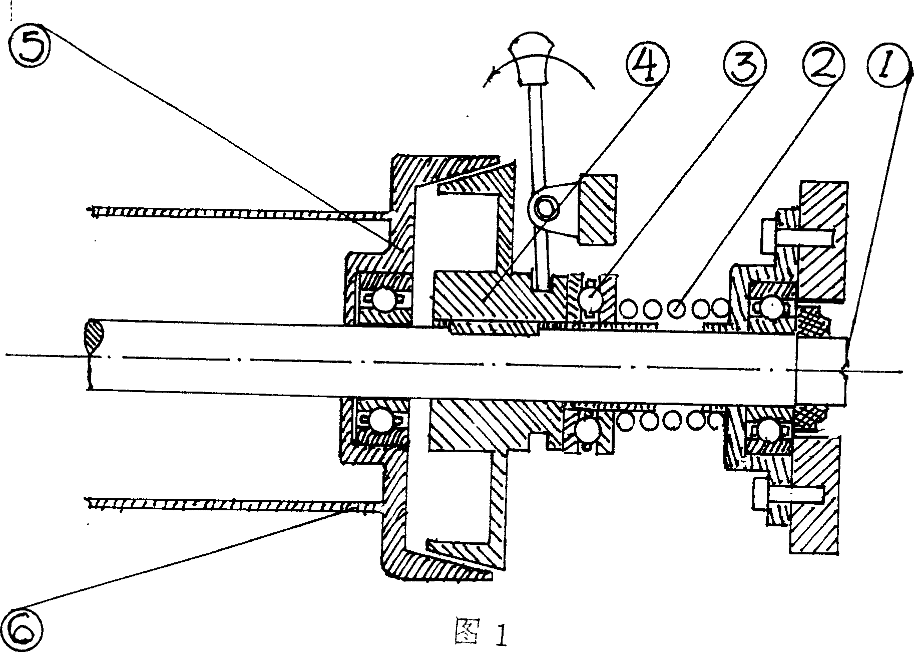
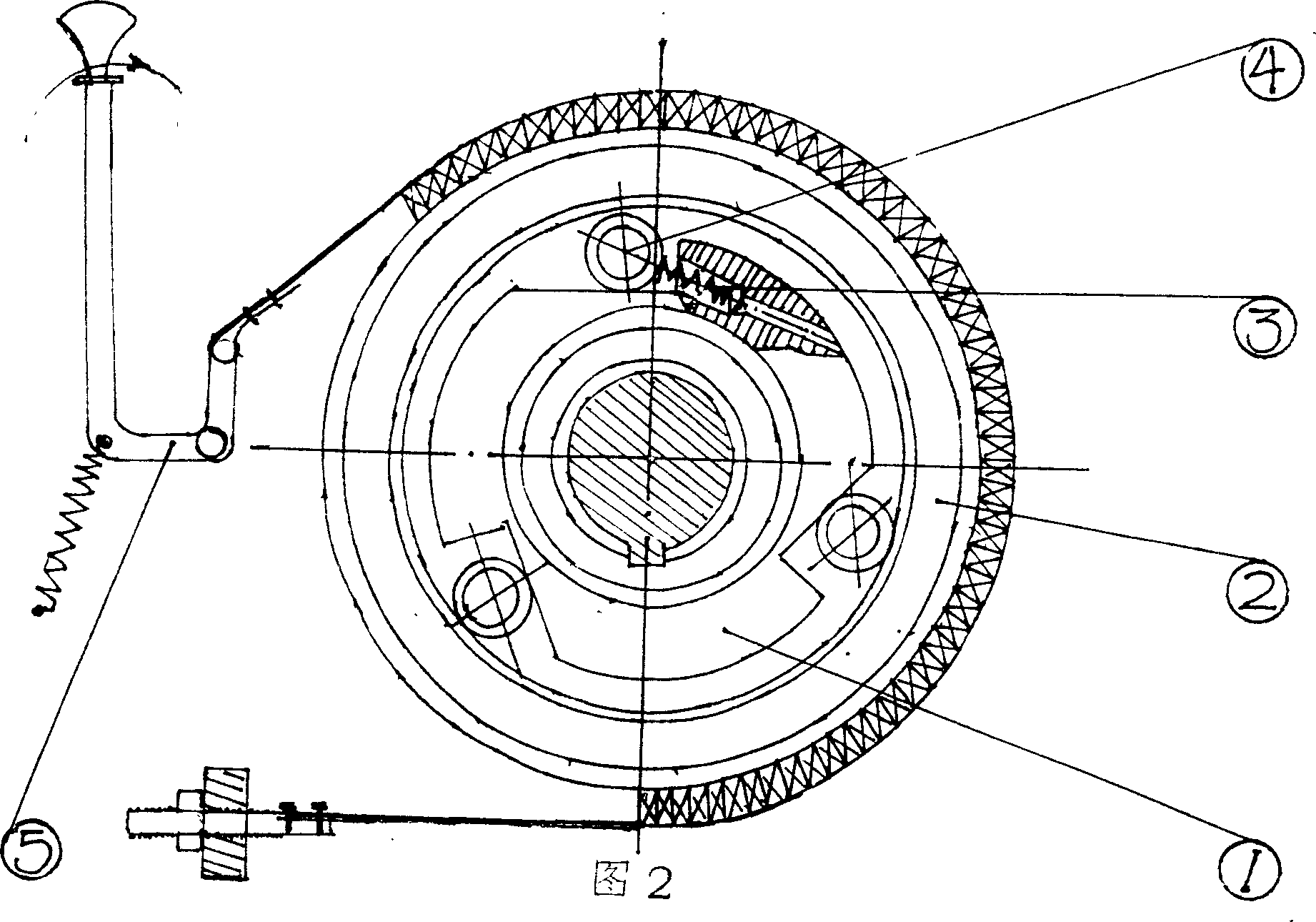
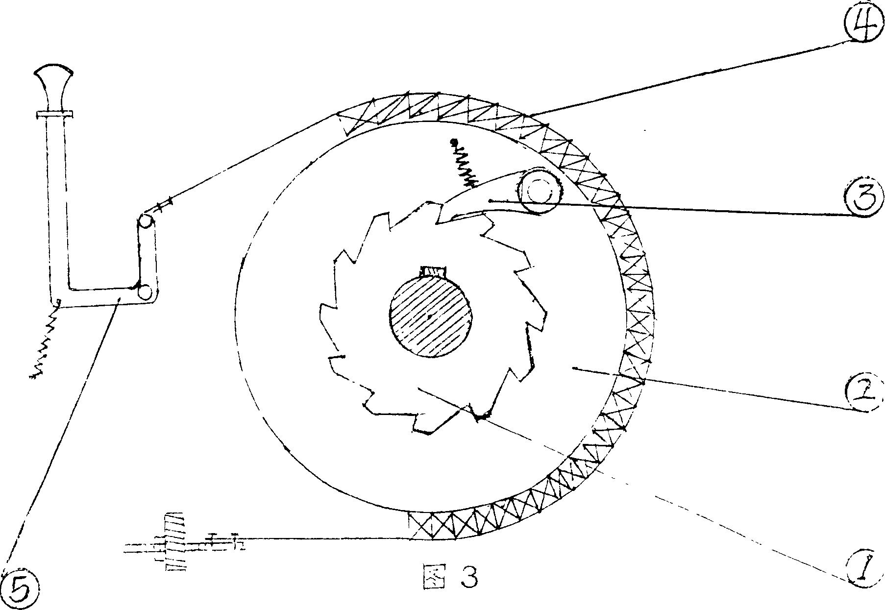
[0012] In Fig. 1, 1. output shaft; 2. spring; 3. thrust bearing; 4. inner cone; 5. outer cone; 6. reel.

[0013] The output shaft ① is obtained by connecting the shaft coupling with the worm gear shaft or directly lengthening the worm gear shaft. The two ends of the spring ② are respectively set between the thrust bearing ③ and the bearing seat, the thrust bearing ③ is set on one end of the inner cone ④, and the inner cone ④ is set on the output shaft ① by a guide flat key or a spline. Outer cone 5. is fixed on one end (or cast into one) of reel 6. is combined with output shaft 1. by bearing. In the stopped position, due to the thrust of the spring, the inner and outer cones are in a joint state, and the reel rotates with the output shaft under the action of friction torque. If the handle is pushed to the left, the inner and outer cones are in a separated state, and the reel The cylinder can be rotated arbitrarily, because the worm and worm gear have the ability of "self-lock...


PUM


Abstract

A clutch-type brake arranged on the drive shaft for having the functions of both clutch and brake features that the driven part of friction clutch is fixed to spool, a band brake is arranged on the driven part of overriding clutch, the ratchet mechanism is used in conjunction with the band friction mechanism, and the ratchet mechanism is installed in the planetary clutch. It is used for hoister.

Description

technical field [0001] The invention relates to a brake, which is a combination of a clutch mechanism and a friction brake mechanism, especially when used in lifting equipment, it can produce "self-locking" to prevent reverse rotation, no braking device is required, and the weight will not fall. The starting power is controlled by the handle, it can fall freely, the falling speed is fast under light load, and the clutch brake can be dropped without load. Background technique [0002] It is well known that electronically controlled brakes cannot be used because they are not electric. When other types of brakes are used on lifting equipment, when the power stops, they will not produce "self-locking" and will reverse. The brake must be operated immediately to control, which brings inconvenience to the operation. It is unsafe and labor-intensive; although the worm gear is used as the transmission device of the crane, it has the function of "self-locking", but it is not powered a...

Claims


Application Information

Patent Timeline
Patent Type & Authority Applications(China)
IPC IPC(8): B66D5/02
Inventor 王升国王升权王红王升起李玉芝王长运
Owner 李玉芝
Why Eureka
Try Eureka