Winding apparatus for divided stator core

A technology of stator iron core and winding device, which is applied to electromechanical devices, manufacturing motor generators, electrical components, etc., can solve the problems of complicated operation, poor handling of iron core components, and poor operability.

Active Publication Date: 2006-03-15
TOYO DENSO
View PDF1 Cites 4 Cited by
  • Summary
  • Abstract
  • Description
  • Claims
  • Application Information

AI Technical Summary

Problems solved by technology

[0009] The problem to be solved is that in the split stator core, the split stator core cannot ensure sufficient clearance for passing the coils between the claws of the individual core elements in the assembled state, and there is the following complicated operation The problem is that the coils are wound on each core element separately in advance, and the wiring of each coil end is performed after assembly.
[0010] Moreover, since the method of arranging the divided core elements in a linear form has the following problems, that is, to continuously wind the individual core elements, a special winding device must be used, and the handling of the individual core elements that are continuously wound is reduced. Poor, poor operability when assembling them into one body

Method used


Image

  • Winding apparatus for divided stator core
  • Winding apparatus for divided stator core
  • Winding apparatus for divided stator core

Examples


Embodiment Construction

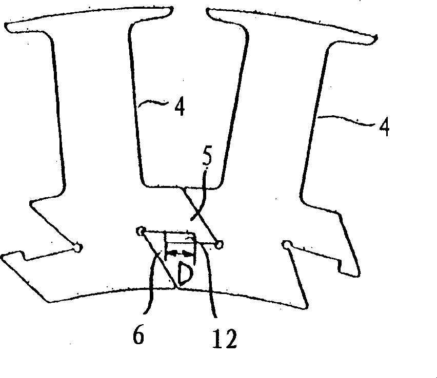
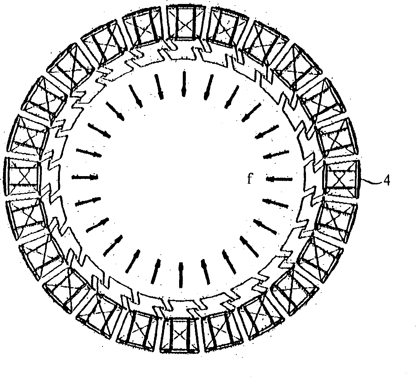
[0026] The coil winding device for split stator core of the present invention, while stepping and conveying a magnetic pole through the drive shaft, the stator core mounted on the drive shaft passes the copper wire between the claws, and winds and installs the coils sequentially and continuously In the magnetic pole part, there is a mechanism for partially expanding the stator core outward sequentially. The stator core and the drive shaft rotate synchronously to combine the various core elements with each other along the circumferential direction within a specified range. Specifically, structured as Figures 6 to 10 shown.

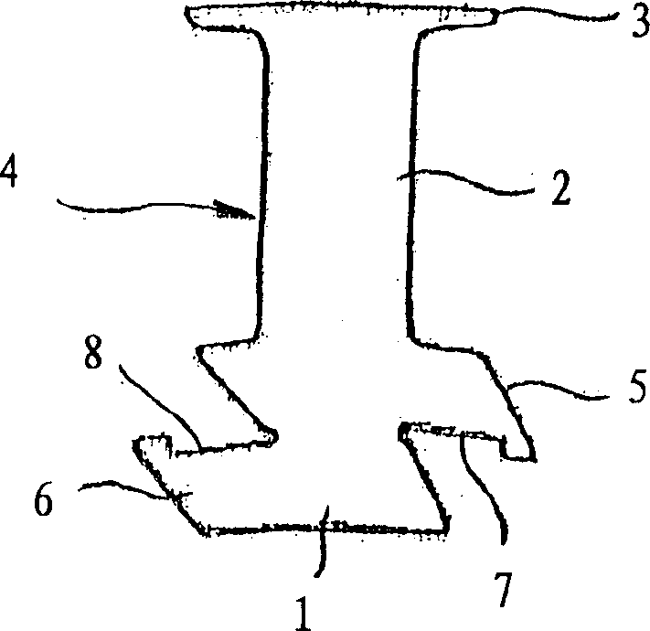
[0027] The mechanism is composed of the following parts: a circular pedestal 13 integrally installed on the drive shaft 12; a rod 15, which is slidably mounted on the pedestal 13 in the direction of the center of the circle through a sliding member 14, and is arranged to Each core element 4 of the divided stator core 9 is opposed to and respectively abutt...


PUM


Abstract

In the winding splitting type stator, the invention can maximally enlarge the claw part in iron core split by pole unit to make the gap between claw parts smaller and to make continuous winding in each pole part at the condition of all iron cores being assembled together. On one side the winding equipment lets the stator iron core mounted on the driving shaft to transfer a pole via the driving shaft, on other side it makes copper wire pass through interval between claws to make continuous winding on pole. The part of stator iron core extending outward is located in the winding device, and all iron cores are assembled along circumferential direction.

Description

technical field [0001] The present invention relates to a winding device for winding a coil on an outer rotor type stator core constituted by a unit structure of a rotating electric machine. Background technique [0002] The prior art discloses a structure (refer to Japanese Patent Document 2001-402936), such as Figures 1 to 4 As shown, in the outer rotor type stator core of the rotating electrical machine, the core element 4 divided into the magnetic pole unit composed of the yoke part 1, the magnetic pole part 2 and the claw part 3 is mutually arranged in the circumferential direction through the yoke part 1. It can be assembled movably within a certain range, unlike the prior art, which is assembled by press-fitting, and each core element can be easily assembled at one time in a state of being arranged in a circle. [0003] Each core element 4 is provided with a downwardly protruding arm portion 5 at the upper stage on one side of the yoke portion 1 and an upwardly proje...

Claims


Application Information

Patent Timeline
Patent Type & Authority Applications(China)
IPC IPC(8): H02K15/08
Inventor 马场秀树藤井隆则福岛健夫
Owner TOYO DENSO
Why Eureka
Try Eureka