
Steam discharge pipeline structure for directly preventing freezing of air condenser in winter

A technology for air-cooled condensers and exhaust pipes, applied in steam/steam condensers, lighting and heating equipment, etc., can solve the problem of easy freezing of steam side channels, affecting the safe operation of air-cooled power plants, and affecting the economic benefits of power generation companies, etc. problems, to achieve the effect of preventing freezing phenomenon, preventing and suppressing large-scale freezing, and improving unit economy

Inactive Publication Date: 2013-05-01
NORTH CHINA ELECTRIC POWER UNIV (BAODING) +1
View PDF5 Cites 3 Cited by
  • Summary
  • Abstract
  • Description
  • Claims
  • Application Information

AI Technical Summary

Problems solved by technology

A large number of engineering practices have shown that when the ambient temperature is lower than 0 degrees Celsius, the steam side channel of the air-cooling unit is prone to freezing, causing damage to the air-cooling fin tube bundle and affecting the safe operation of the air-cooling power station
At present, in order to avoid the above situation, the active units usually adopt high back pressure operation mode, which reduces the economical efficiency of unit operation and seriously affects the economic benefits of power generation enterprises

Method used


Image

  • Steam discharge pipeline structure for directly preventing freezing of air condenser in winter
  • Steam discharge pipeline structure for directly preventing freezing of air condenser in winter
  • Steam discharge pipeline structure for directly preventing freezing of air condenser in winter

Examples


Embodiment Construction

[0021] The present invention provides an exhaust pipe structure for direct air-cooled condensers to prevent freezing in winter. The present invention will be further described below in conjunction with the accompanying drawings and specific embodiments.

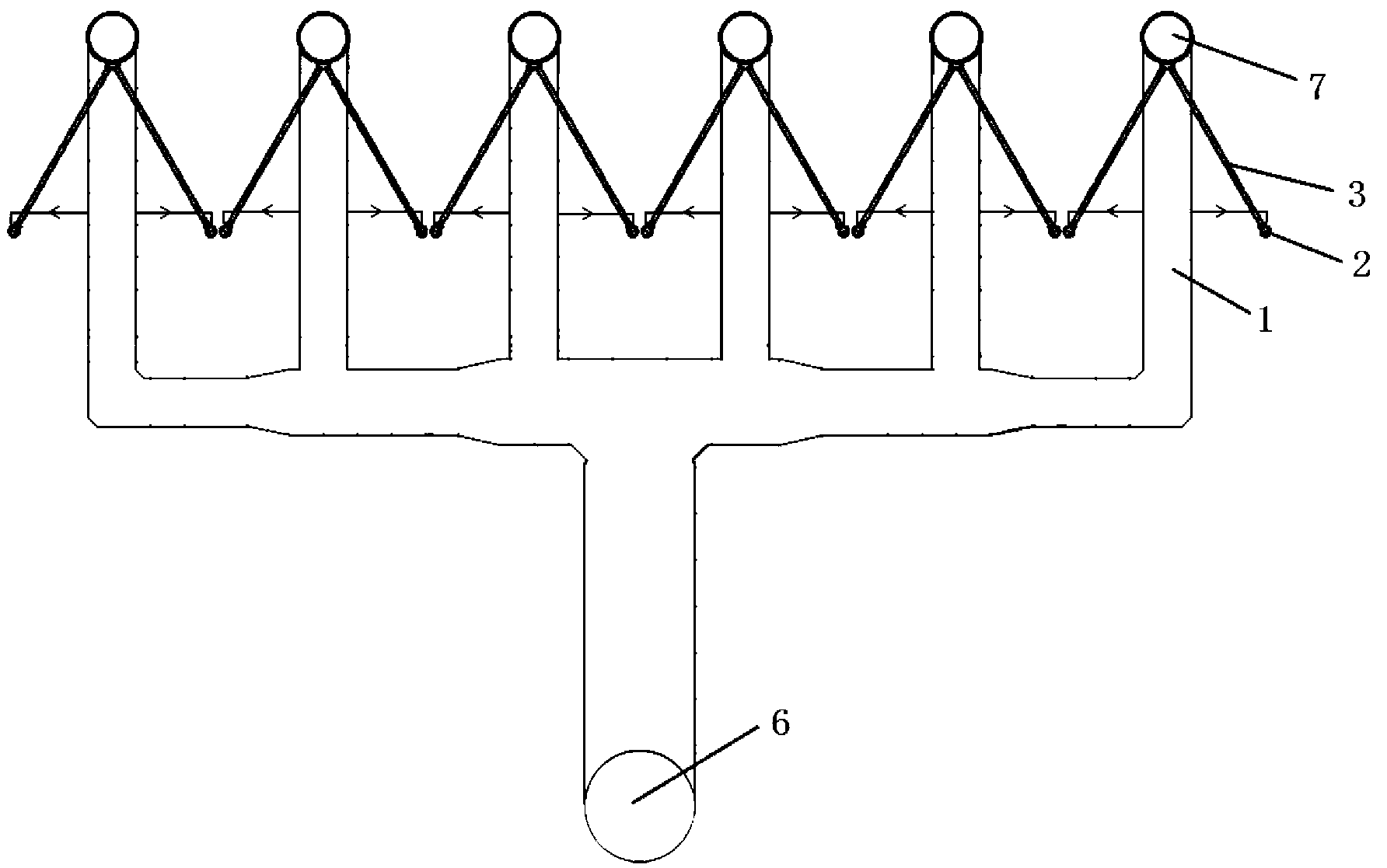
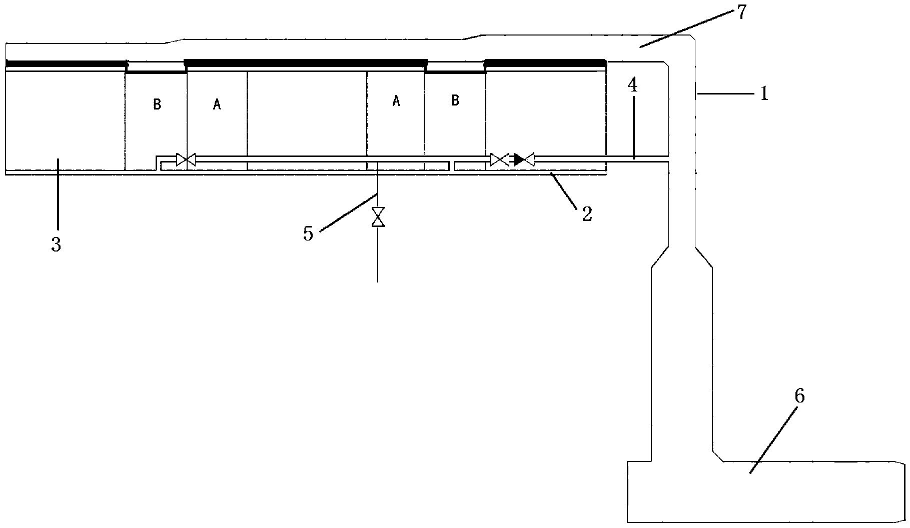
[0022] Such as figure 1 and figure 2 As shown, it is a schematic diagram of the steam turbine exhaust pipe of a 300MW direct air cooling unit. The steam turbine exhaust pipe 6 is connected to the steam distribution pipe 7 of each column of the air-cooled condenser through 6 parallel riser pipes 1, and each steam distribution pipe 7 is connected with 5 groups of condenser units 3 side by side, and each group of condenser units The lower end of 3 is connected through the condensate collection pipe 2; each group of condenser units 3 is divided into two pieces arranged obliquely on the left and right, forming an inverted "V" structure; among the five groups of condenser units 3, the downstream unit and the countercurrent The u...


PUM


Abstract

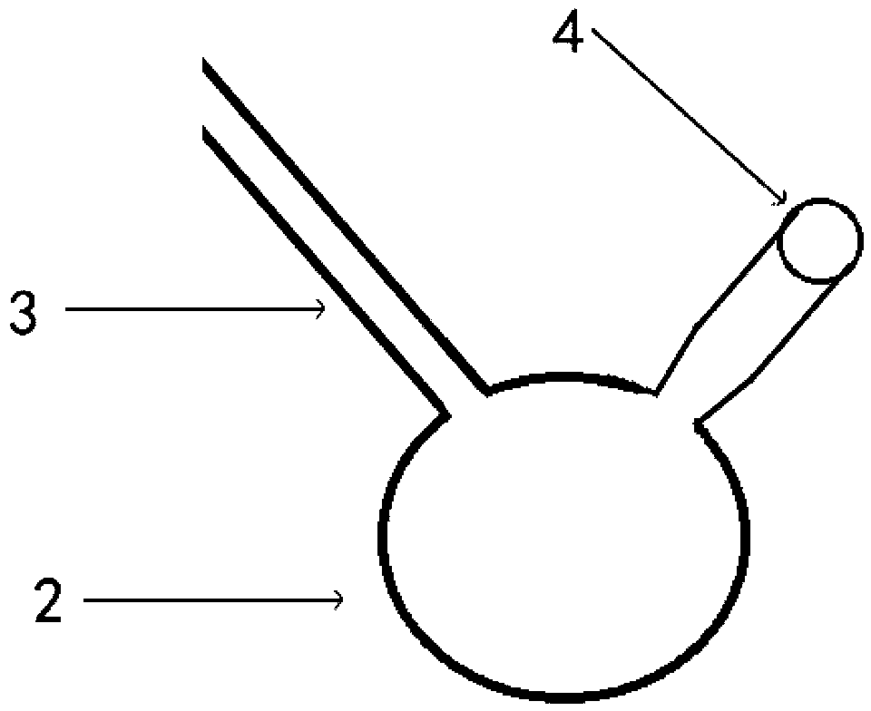
The invention relates to a steam discharge pipeline structure for directly preventing freezing of an air condenser in winter, which belongs to the technical field of energy power. Each group of condenser units is divided into a left sheet and a right sheet, which are obliquely arranged; in an odd-number group of condenser units, fair current units and adverse current units are alternately arranged; one steam leading-out pipeline which is vertical to an ascending pipe and parallel to a steam distribution pipe is led out from each ascending pipe, a branch pipeline which is led out from each steam leading-out pipeline is respectively connected with a condensed water collection pipeline of the adverse current unit part of the condenser unit, and the steam leading-out pipeline is higher than the condensed water collection pipeline in the vertical direction. On the basis that the existing system is not greatly changed, partial steam is led out from the air condenser distribution pipe to be used for improving the distribution characteristics of the air condensed steam units, the large-area freezing of a steam side runner of the air condensation unit can be prevented and inhibited, an effect for rapidly thawing can be realized when the condensed water collection pipeline is frozen, an air cooling unit can be maintained to run safely under the low backpressure simultaneously, and the economical performance can be improved.

Description

technical field [0001] The invention belongs to the technical field of energy and power, and in particular relates to an exhaust pipe structure used for direct air-cooled condensers to prevent freezing in winter. Background technique [0002] Air-cooling technology, as a key technology for developing large-scale, high-parameter coal-fired generating units in the coal-rich and water-deficient areas of northern my country, has developed rapidly with the strong support of relevant national policies. The direct air-cooled condenser uses air instead of water as the cooling medium to cool the exhaust steam of the steam turbine. Due to the low air density, small specific heat, and low thermal conductivity, the air-cooled condenser has a large area and a large number of air-cooled units, which are easily affected by external environmental factors during operation. A large number of engineering practices have shown that when the ambient temperature is lower than 0 degrees Celsius, t...

Claims


Application Information

Patent Timeline
IPC IPC(8): F28B9/02
Inventor 杜小泽水海波邓红周张涛席新铭梁建军杨立军杨勇平
Owner NORTH CHINA ELECTRIC POWER UNIV (BAODING)
Learn More