Fluid mixing apparatus and fluid mixing method

a fluid mixing and fluid technology, applied in the field of fluid mixing apparatus and fluid mixing method, can solve the problems of insufficient uniform distribution of fluid, inability to perform uniform and stable mixing or reaction in microchannels, and difficulty in uniform distribution of fluid to all channels, so as to achieve uniform and stable mixing or reaction, increase the numbering-up and air bubble removal properties in the channels, and uniform distribution of fluids

Active Publication Date: 2010-08-24
FUJIFILM CORP
View PDF9 Cites 3 Cited by
  • Summary
  • Abstract
  • Description
  • Claims
  • Application Information

AI Technical Summary

Benefits of technology

[0012]This prevents continuous stable operation, and also requires time for starting the operation or cleaning after the operation, which increases losses of a reaction fluid or a cleaning fluid.
[0034]According to the present invention, uniform distribution properties of the fluids in numbering-up and air bubble removing properties in the channels can be increased to allow uniform and stable mixing or reaction to be performed.

Problems solved by technology

The conventional method, however, is still insufficient to uniformly distribute a fluid, and uniform and stable mixing or reaction cannot be performed in microchannels.
Thus, it is difficult to uniformly distribute the fluid to all channels by the fluid pushing air in the channels at the start of passing the fluid (removal of air), or to remove air bubbles trapped during operation from the buffer or channels communicating with the buffer (removal of air bubbles).
This prevents continuous stable operation, and also requires time for starting the operation or cleaning after the operation, which increases losses of a reaction fluid or a cleaning fluid.
The method including the buffer is generally inappropriate for a fluid having a quality degrading with time.

Method used


Image

  • Fluid mixing apparatus and fluid mixing method
  • Fluid mixing apparatus and fluid mixing method
  • Fluid mixing apparatus and fluid mixing method

Examples


first embodiment

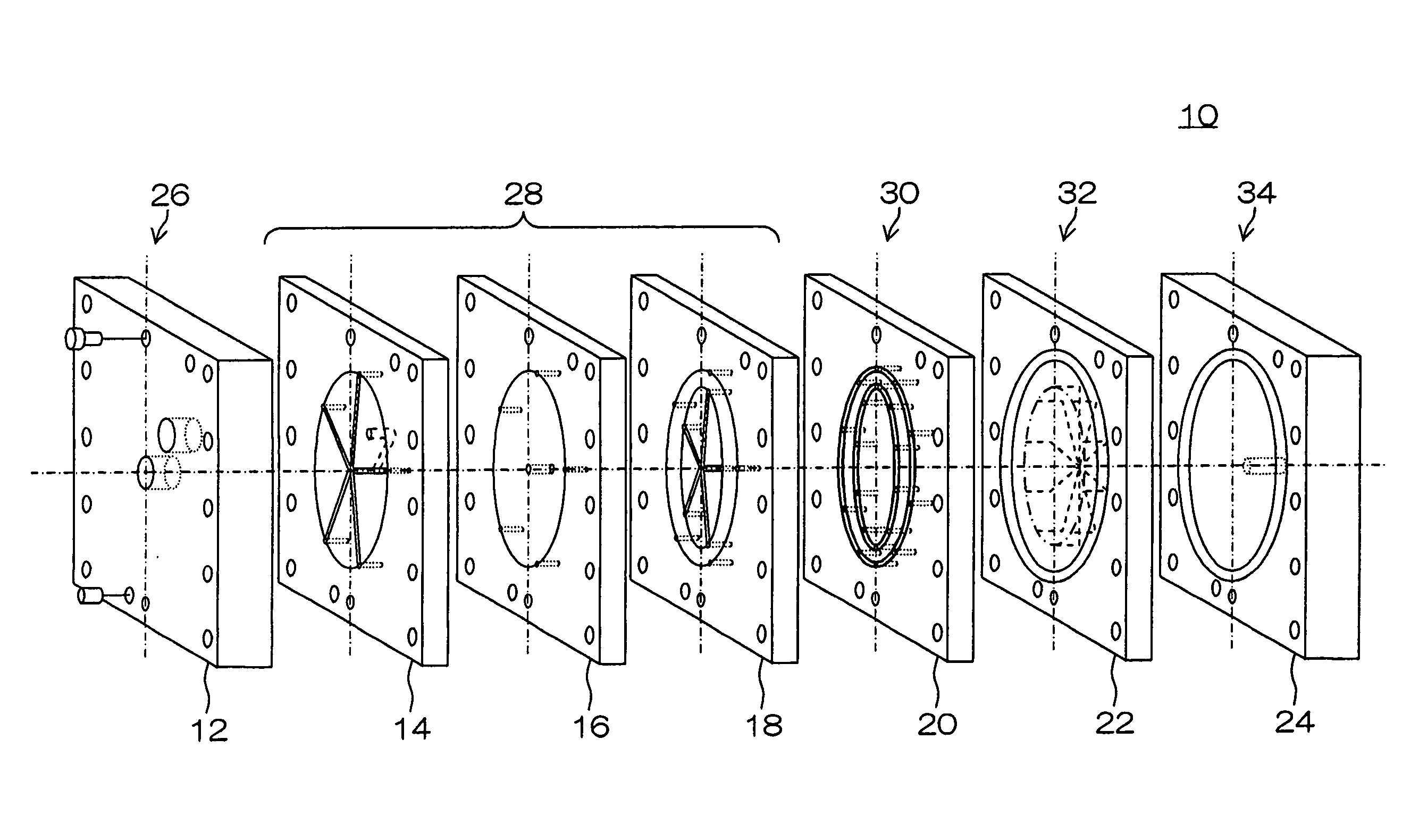
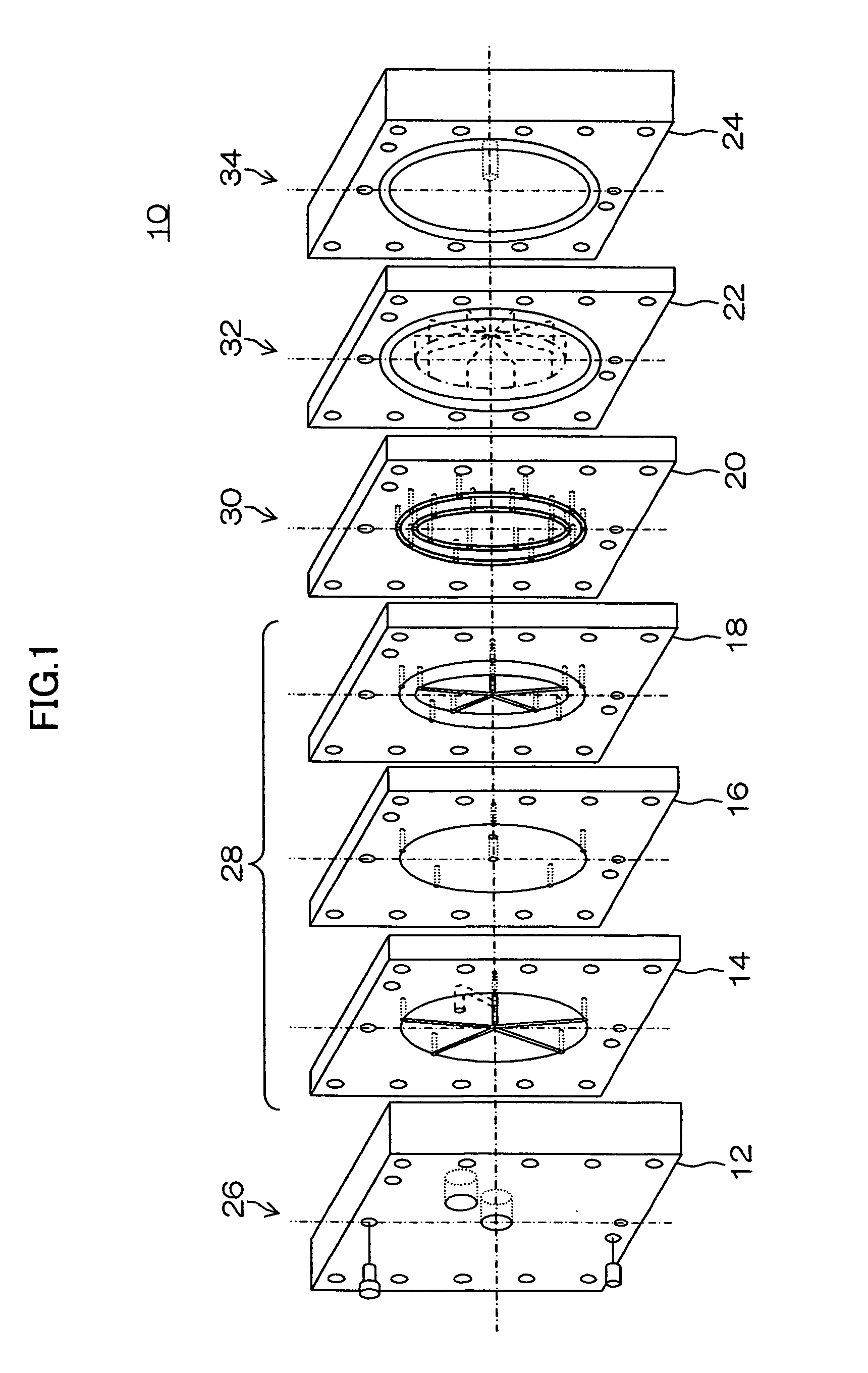
[0045]FIG. 1 is an exploded perspective view for illustrating an example of a fluid mixing apparatus (microreactor unit) 10 of numbering-up type according to a first embodiment. Seven parts that constitute the fluid mixing apparatus 10 are herein shown in exploded perspective view. This embodiment will be described by taking an example of a converging section and a mixing / reaction section integrally formed in one plate.

[0046]As shown, the fluid mixing apparatus 10 is constituted by at least seven plates 12, 14, 16, 18, 20, 22 and 24 stacked and integrated. The fluid mixing apparatus 10 generally includes an inflow section 26 through which liquids L1 and L2 flow in, a rectifying section 28 that rectifies the flowed-in liquids L1 and L2 into concentric annular flows, a distribution section 30 that distributes the rectified concentric annular flows into a plurality of flows, a mixing / reaction section 32 that converges the distributed liquids L1 and L2 to cause mixing or reaction, and a...

second embodiment

[0095]FIG. 7 is an exploded perspective view for illustrating an example of a fluid mixing apparatus 10′ of numbering-up type according to a second embodiment. Eight parts that constitute the fluid mixing apparatus 10′ are herein shown in exploded perspective view. In this embodiment, an example of a converging section and a mixing / reaction section being formed in different plates will be described. The same members or components having the same functions as the first embodiment are designated by the same reference numerals, and detailed descriptions thereof will be omitted.

[0096]The fluid mixing apparatus 10′ in FIG. 7 is configured as the first embodiment in FIG. 1 except that plates have circular shapes and a plate 82 is added.

[0097]The plate 82 that constitutes a converging section 31 has, in a surface facing a plate 20, ten small concentric annular channels 84 . . . and 86 . . . communicating with first distribution holes 62′ . . . and 64′ . . . that divide concentric annular c...


PUM

PropertyMeasurementUnit
diameteraaaaaaaaaa
diameteraaaaaaaaaa
depthaaaaaaaaaa

Abstract

The present invention provides a fluid mixing apparatus having a numbering-up mechanism that distributes plural kinds of fluids and concurrently performs multiple mixing or reactions, comprising: a rectifying section having a plurality of annular channels that rectify the plural kinds of fluids into respective concentric annular flows; a distribution section having a plurality of distribution channels that distribute the plural kinds of fluids rectified by the rectifying section into a plurality of flows; a converging section having a plurality of converging channels that converge different kinds of fluids among the plural kinds of fluids distributed by the distribution section; and a mixing / reaction section having a plurality of mixing / reaction channels that cause mixing or reaction of the plural kinds of fluids converged by the converging section, wherein a plurality of pressure loss increasing devices are provided in the distribution channels.

Description

BACKGROUND OF THE INVENTION[0001]1. Field of the Invention[0002]The present invention relates to a fluid mixing apparatus and a fluid mixing method, and more particularly to a fluid mixing apparatus and a fluid mixing method for distributing a fluid at a uniform flow rate in branch portions of a channel in the fluid mixing apparatus. More particularly, the present invention relates to a fluid mixing method for uniformly distributing a fluid to increase yields in a fluid mixing apparatus of numbering-up type including an increased number of units (referred to as microreactors) for precise chemical reactions or mixing.[0003]2. Description of the Related Art[0004]Micro space provides a large surface area per unit volume, allowing many reaction interfaces of reaction fluids to be formed and facilitating temperature control, which receives attention as a technique for increasing efficiency or velocity of reactions or mixing between fluids.[0005]Generally, a microreactor that performs rea...

Claims


Application Information

Patent Timeline
Patent Type & Authority Patents(United States)
IPC IPC(8): B01J19/00B01J8/02B01F5/06
CPCB01F5/0453B01F5/046B01F13/0067B01J19/0093B01J2219/00783B01J2219/00819B01J2219/00862B01J2219/00889B01J2219/00891B33Y80/00B01F25/31324B01F25/3132B01F33/30121
Inventor FUJIWARA, TAKAYUKIOKUTSU, KAZUO
Owner FUJIFILM CORP
Why Eureka
Try Eureka