Matched transmission line connector

A technology for transmission lines and electrical connections, which is used in connection devices, circuits, waveguide-type devices, etc., and can solve problems such as high cost and unrealistic active impedance matching networks.

Inactive Publication Date: 2006-03-15
奥普林克通讯股份有限公司
View PDF0 Cites 6 Cited by
  • Summary
  • Abstract
  • Description
  • Claims
  • Application Information

AI Technical Summary

Problems solved by technology

Interconnects designed to support broadband communications require costly and impractical active impedance

Method used


Image

  • Matched transmission line connector
  • Matched transmission line connector
  • Matched transmission line connector

Examples


Embodiment Construction

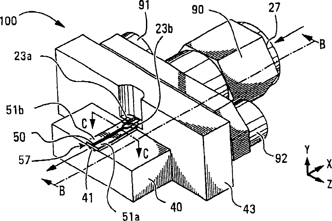
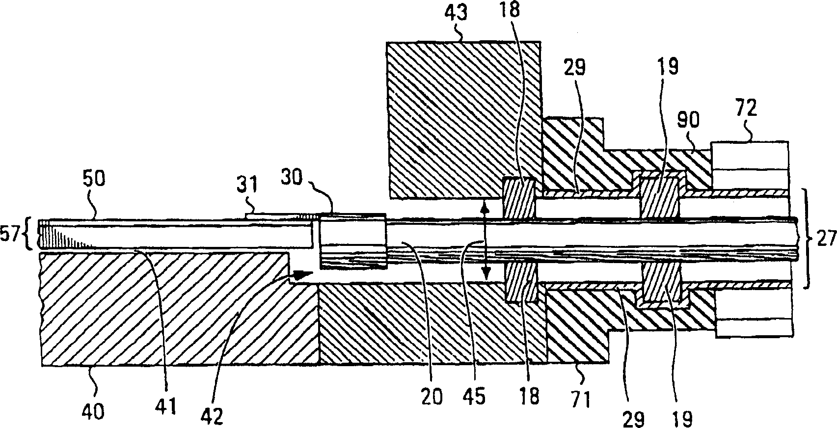
[0027] Referring to FIG. 1, there is shown an interconnect device 100 bidirectionally connecting a coplanar waveguide (CPW) 57 to a coaxial transmission line 27 designed in accordance with the present invention. Because the interconnection device 100 is bidirectional microwave power (electromagnetic waves), which can be emitted from the CPW 57 or the coaxial transmission line 27 through the interconnection device 100, and then go to other transmission lines.

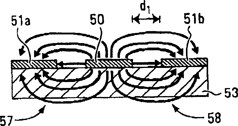
[0028] Figure 1C and 1D The cross-sections of the CPW and the coaxial transmission line 27 are shown, respectively. refer to Figure 1C , CPW 57 consists of a centerline 50 (or trace) and two coplanar ground planes 51a and 51b. Each ground plane 51a and 51b is separated from the centerline 50 by a small distance d 1 , so that the center line 50 and the base surfaces 51a and 51b constitute a transmission line. Centerline 50 and ground planes 51a and 51b are located on top of dielectric substrate 53 . The dielectric...


PUM


Abstract

According to the invention there is provided an interconnect for bi-directionally coupling together a coaxial transmission line and a coplanar waveguide. The interconnect is adapted to provide a transition region between the coaxial transmission line and the coplanar waveguide, which induces a smooth transition from the electric field of the coaxial transmission line to the electric field of the coplanar waveguide as well as broadband impedance matching between the coaxial transmission line and coplanar waveguide.

Description

technical field [0001] The present invention generally relates to the design of an interconnection device for communication products, especially an interconnection device between different types of transmission lines. Background technique [0002] The general trend of communication technology development is to enable new products to support higher transmission capabilities than old products. Typically, supporting higher levels of transmission capability involves new products being operable over wider frequency bands (ie, bandwidth) than older products. In addition, due to increasing bandwidth requirements, the physical design (geometry) of the building blocks that make up new products—from microchips and cables to packaging—has an increasing impact on the transmission capabilities they can withstand. [0003] In particular, the physical interconnect that connects different products together is a significant bottleneck that limits the operational bandwidth of the products. ...

Claims


Application Information

Patent Timeline
IPC IPC(8): H03H7/38H01P5/00H01P5/08
CPCH01P5/085
Inventor 曾·A·古延阿南德·冈达瓦贾拉威廉·D·布什托马斯·马修刘天功王同清莫尼·G·马修
Owner 奥普林克通讯股份有限公司
Why Eureka
Try Eureka