Method and system for dynamic range detection and positioning utilizing leaky wave antennas
What is Al technical title?
Al technical title is built by PatSnap Al team. It summarizes the technical point description of the patent document.
a dynamic range detection and leaky wave technology, applied in the field of wireless communication, can solve the problems of power inefficiency of transmitters and/or receivers in comparison to other blocks of portable communication devices
Inactive Publication Date: 2010-12-09
AVAGO TECH INT SALES PTE LTD
View PDF98 Cites 57 Cited by
Summary
Abstract
Description
Claims
Application Information
AI Technical Summary
This helps you quickly interpret patents by identifying the three key elements:
Problems solved by technology
Method used
Benefits of technology
[0011]A system and/or method for dynamic range detection and positioning utilizing leaky wave antennas as sh...
Problems solved by technology
Additionally, transmit and/or receive circuitry within such mobile wireless devices often account for a significant portion of the power consumed within these devices.
Mor...
Method used
Image
Click on the blue label to locate the original text in one second.
Reading with bidirectional positioning of images and text.
Examples
Embodiment Construction
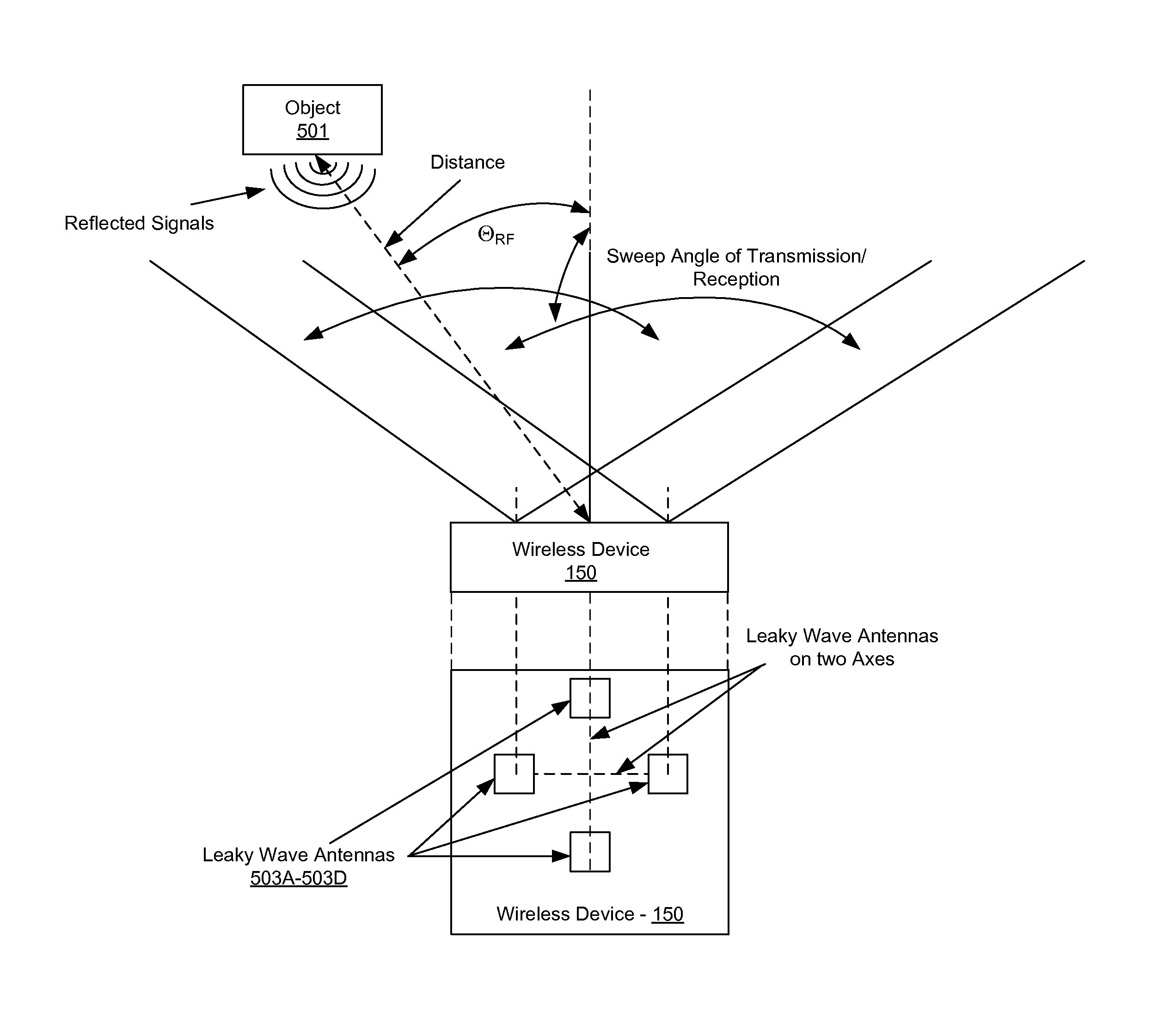
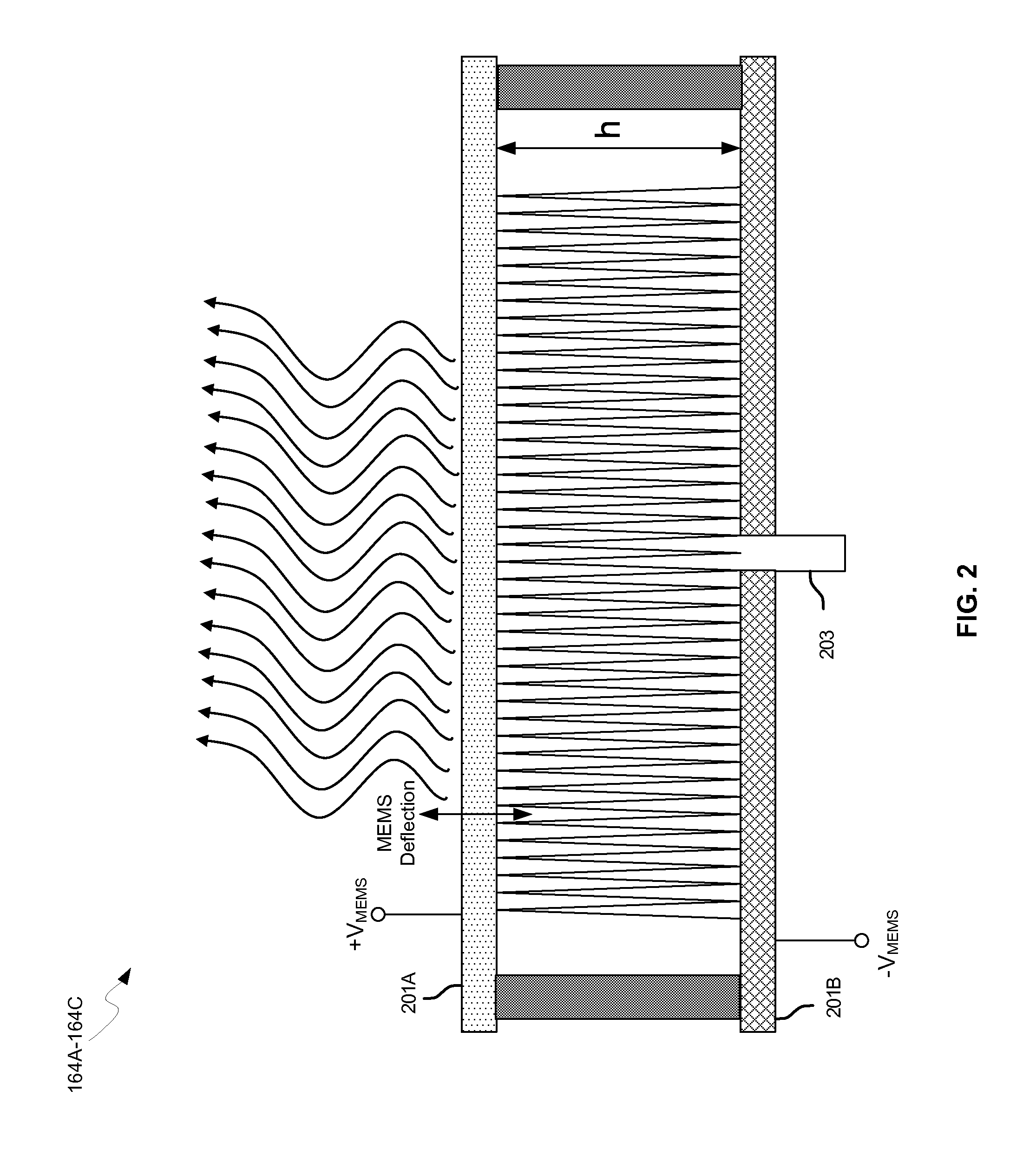
[0023]Certain aspects of the invention may be found in a method and system for dynamic range detection and positioning utilizing leaky wave antennas. Exemplary aspects of the invention may comprise configuring one or more leaky wave antennas to enable communication of signals in a particular direction. RF signals that are reflected from an object may be received via the configured one or more leaky wave antennas, and a location of the object may be determined based on the received reflected RF signals. The velocity of the object may be determined based on a Doppler shift associated with the received reflected RF signals. A frequency may be chirped of an RF signal transmitted by the configured one or more leaky wave antennas. A location of the object may be determined based on the received reflected RF signals resulting from the chirping of the frequency of the transmitted RF signal. A resonant frequency of the one or more leaky wave antennas may be configured utilizing micro-electro...
PUM
Abstract
Methods and systems for dynamic range detection and positioning utilizing leaky wave antennas (LWAs) are disclosed and may include configuring one or more LWAs to enable communication of signals in a particular direction. RF signals that are reflected from an object may be received via the LWAs, and a location of the object may be determined based on the received reflected RF signals. The velocity of the object may be determined based on a Doppler shift associated with the received reflected RF signals. A frequency chirped signal may be transmitted by the LWAs to determine a location of the object. A resonant frequency of the LWAs may be configured utilizing micro-electro-mechanical systems (MEMS) deflection. LWAs may be situated along a plurality of axes in the wireless device. The LWAs may include microstrip or coplanar waveguides, where a cavity height is dependent on spacing between conductive lines in the waveguides.
Description
CROSS-REFERENCE TO RELATED APPLICATIONS / INCORPORATION BY REFERENCE[0001]This application makes reference to, claims the benefit from, and claims priority to U.S. Provisional Application Ser. No. 61 / 246,618 filed on Sep. 29, 2009, and U.S. Provisional Application Ser. No. 61 / 185,245 filed on Jun. 9, 2009.[0002]This application also makes reference to:U.S. patent application Ser. No. 12 / 650,212 filed on Dec. 30, 2009;U.S. patent application Ser. No. 12 / 650,295 filed on Dec. 30, 2009;U.S. patent application Ser. No. 12 / 650,277 filed on Dec. 30, 2009;U.S. patent application Ser. No. 12 / 650,192 filed on Dec. 30, 2009;U.S. patent application Ser. No. 12 / 650,224 filed on Dec. 30, 2009;U.S. patent application Ser. No. 12 / 650,176 filed on Dec. 30, 2009;U.S. patent application Ser. No. 12 / 650,246 filed on Dec. 30, 2009;U.S. patent application Ser. No. 12 / 650,292 filed on Dec. 30, 2009;U.S. patent application Ser. No. 12 / 650,324 filed on Dec. 30, 2009;U.S. patent application Ser. No. 12 / 708,36...
Claims
Application Information
Patent Timeline
Application Date:The date an application was filed.
Publication Date:The date a patent or application was officially published.
First Publication Date:The earliest publication date of a patent with the same application number.
Issue Date:Publication date of the patent grant document.
PCT Entry Date:The Entry date of PCT National Phase.
Estimated Expiry Date:The statutory expiry date of a patent right according to the Patent Law, and it is the longest term of protection that the patent right can achieve without the termination of the patent right due to other reasons(Term extension factor has been taken into account ).
Invalid Date:Actual expiry date is based on effective date or publication date of legal transaction data of invalid patent.