Radio frequency identification tag and diaper, absorber and sensing system using the same

a radio frequency identification and diaper technology, applied in the field of diapers, absorbers and sensing systems, can solve the problems of ineffective manual check-up, increased risk of urinary tract infection, and inconvenient use for users

Active Publication Date: 2013-05-16
IND TECH RES INST
View PDF1 Cites 60 Cited by
  • Summary
  • Abstract
  • Description
  • Claims
  • Application Information

AI Technical Summary

Problems solved by technology

In general, diapers and urine pads, whether being used by infants, the elder with disabilities, or even the invalid, must be replaced frequently, otherwise the users may be susceptible to diaper rash or skin disease, which may even progress into a urinary tract infection.
A long-term care institution, overcrowded with those under care and suffering from a shortage of nursing personnel, is incapable of immediately identifying which of those under care needs to change his / her diaper, and the risk of urinary tract infection is thus increased.
On the other hand, a center-wide, manual check-up is far inefficient.
For all currently available paper diapers, inclusive of the diapers with color rendering structure, one still has to take initiative to check frequently whether urine wetness is indicated, and this is indeed a great burden and pressure to the parents or caregivers.

Method used


Image

  • Radio frequency identification tag and diaper, absorber and sensing system using the same
  • Radio frequency identification tag and diaper, absorber and sensing system using the same
  • Radio frequency identification tag and diaper, absorber and sensing system using the same

Examples


first embodiment

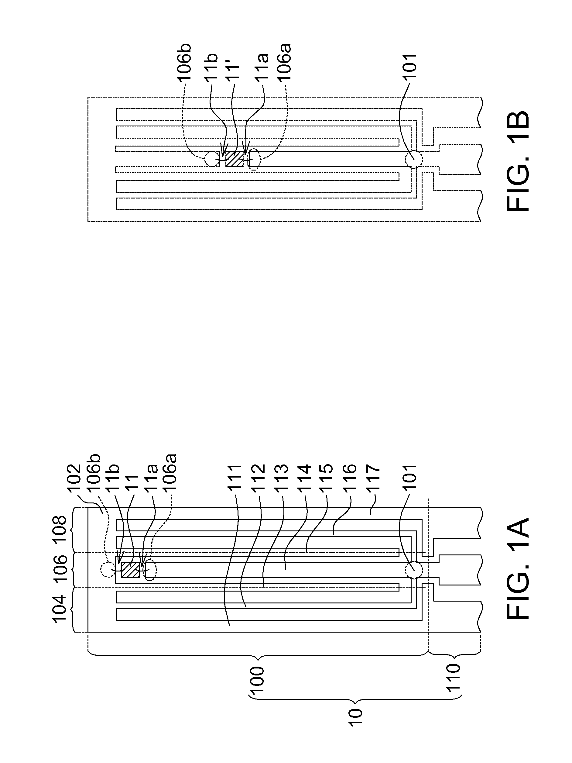
[0025]Referring to FIGS. 1A and 1B, schematic diagrams of coplanar waveguide structures according to an embodiment of the disclosure are shown. The coplanar waveguide structure 10 includes an impedance match portion 100 and a transmission portion 110. The impedance match portion 100 has an input end 101 and a ground plane 102. The impedance of the input end 101 matches the input impedance of the transmission portion 110. The interior of the impedance match portion 100 at least includes three neighboring transmission lines, namely, a first shorted transmission line 104, an RF signal transmission line 106 and a second shorted transmission line 108 arranged from left to right in sequence. The three neighboring transmission lines are respectively formed by a plurality of neighboring metal conductors, namely, a first ground conductor 111, a first signal conductor 112, a second ground conductor 113, a second signal conductor 114, a third ground conductor 115, a third signal conductor 116 ...

second embodiment

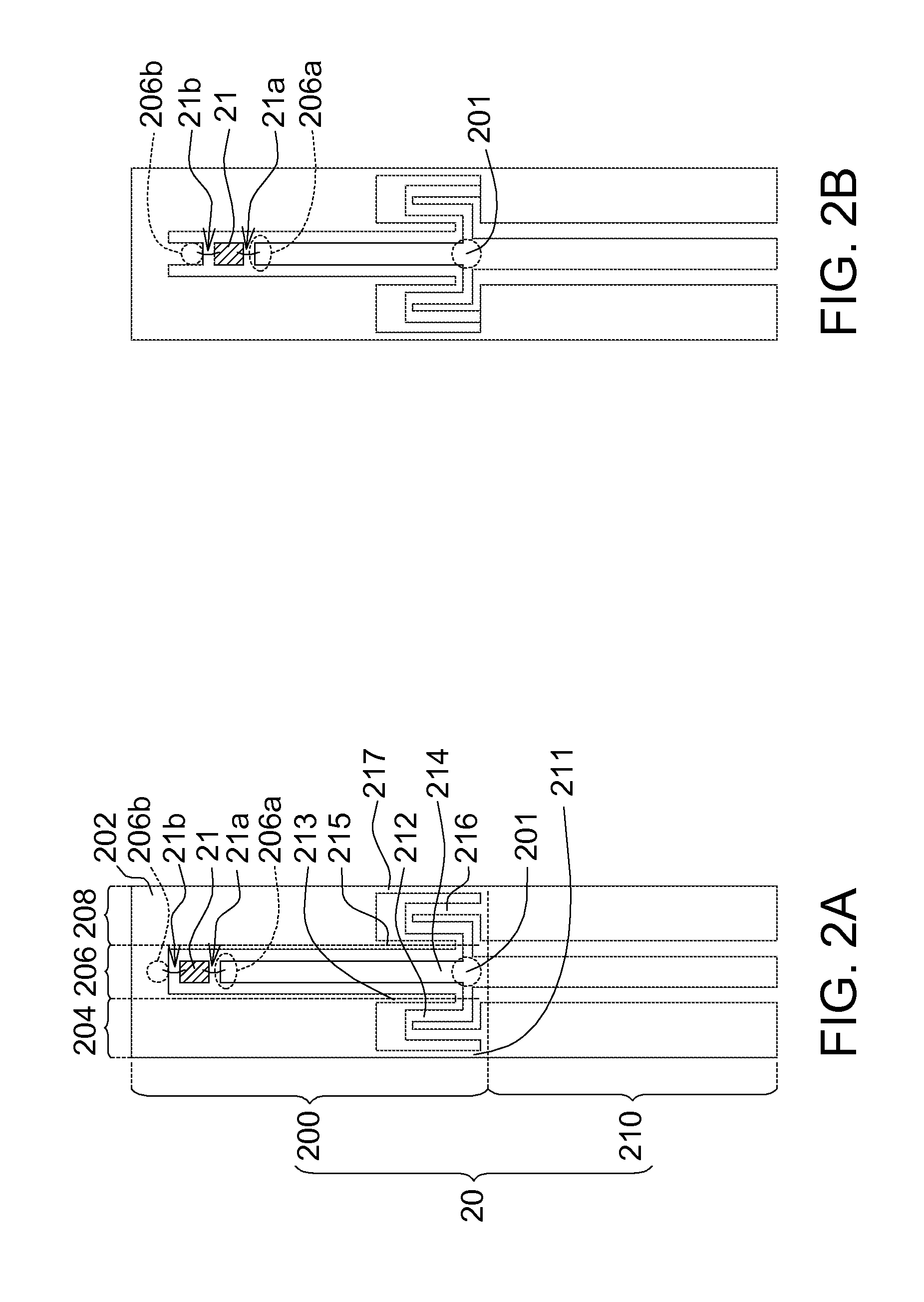
[0029]Referring to FIGS. 2A and 2B, schematic diagrams of coplanar waveguide structure 20 according to an embodiment of the disclosure are shown. The coplanar waveguide structure 20 includes an impedance match portion 200 and a transmission portion 210. The differences between the impedance match portion 200 of the present embodiment and the impedance match portion 100 of the first embodiment are as follows. In the present embodiment, the first signal conductor 212 and the third signal conductor 216 are extended in an S shape instead of a long strip. The ground plane 202, extended to two opposite sides of the second signal conductor 214, is coupled to the first ground conductor 211, the second ground conductor 213, the third ground conductor 215, and the fourth ground conductor 217 respectively to from a common ground plane. The first signal conductor 212 is coupled between the input end 201 and the first ground conductor 211. The first signal conductor 212 and its neighboring groun...

application example

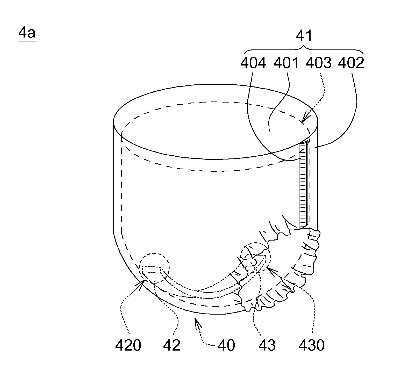
[0038]Referring to FIGS. 4A-4B and 5A-5B. FIGS. 4A-4B respectively are schematic diagrams of wetness sensing diapers according to an application example of the disclosure. FIGS. 5A-5B respectively are schematic diagrams of wetness sensing absorbers according to another application example of the disclosure. In each application example, any of the RF identification tags 3a-3c illustrated in FIGS. 3A-3C may be used in the urine wetness sensing diapers 4a-4b or the wetness sensing absorbers 5a-5b. The designations inside and outside a parentheses are used for different application examples. The body 41 of the wetness sensing diapers 4a-4b and the body 51 of the wetness sensing absorbers 5a-5b respectively include an inner layer 401 (501), an outer layer 402 (502) and an absorber 403 (503). The inner layer 401 (501) is liquid permeable to keep the surface dry and cozy. The outer layer 402 (502) is liquid impermeable and is formed by such as a water-proof PE film such blocks the leakage ...


PUM


Abstract

A radio frequency (RF) identification tag including a substrate, a planar antenna, an RF chip, a plurality of signal conductors and a plurality of ground conductors is provided. The RF chip receives an RF signal from the planar antenna to generate an identification code. The signal conductors are coupled to the planar antenna. The ground conductors, interlaced on two opposite sides of the signal conductors, and the signal conductors are adjacent to each other and disposed on the substrate to form a coplanar waveguide structure which includes an impedance match portion and a transmission portion. The impedance match portion has an input end coupled to the signal conductors and a ground plane coupled to the ground conductors. The RF chip is disposed between the input end and the ground plane. The transmission portion is connected between the impedance match portion and the planar antenna.

Description

[0001]This application claims the benefit of Taiwan application Serial No. 100141919, filed Nov. 16, 2011, the disclosure of which is incorporated by reference herein in its entirety.BACKGROUND[0002]1. Technical Field[0003]The disclosed embodiments relate in general to a diaper, an absorber and a wetness sensing system, and more particularly to a radio frequency (RF) identification tag with coplanar waveguide structure, and a diaper, an absorber and a sensing system using the same.[0004]2. Description of the Related Art[0005]In general, diapers and urine pads, whether being used by infants, the elder with disabilities, or even the invalid, must be replaced frequently, otherwise the users may be susceptible to diaper rash or skin disease, which may even progress into a urinary tract infection. A long-term care institution, overcrowded with those under care and suffering from a shortage of nursing personnel, is incapable of immediately identifying which of those under care needs to ch...

Claims


Application Information

Patent Timeline
Patent Type & Authority Applications(United States)
IPC IPC(8): A61F13/42G06K19/077
CPCH01Q1/2225H01Q9/285H01Q1/273
Inventor YU, JIUN-JANGCHEN, CHIUNG-HSIUNGLU, CHUN-ANLIN, HONG-CHING
Owner IND TECH RES INST
Why Eureka
Try Eureka