Conveying accelerator

An accelerator and pressure chamber technology, applied in the direction of conveyors, conveying bulk materials, transportation and packaging, etc., can solve the problems of uneven pulverized coal, low transmission power, insufficient combustion, etc., achieve wide application, clean gas, and improve transportation effect of ability

Inactive Publication Date: 2006-03-29
孙付江
View PDF0 Cites 3 Cited by
  • Summary
  • Abstract
  • Description
  • Claims
  • Application Information

AI Technical Summary

Problems solved by technology

At present, the pulverized coal conveying devices of the existing boilers all adopt the structure of fans and pipelines. The disadvantages of this structure are: the transmission power is small, and the pulverized coal sent to the furnace is not uniform, and the combustion is insufficient, resulting in energy waste.
In pipeline transportation, due to the long distance to be transported, the use of fans cannot achieve the purpose. At present, there is no feasible transportation device for long-distance powder ash pipeline transportation.

Method used


Image

  • Conveying accelerator
  • Conveying accelerator
  • Conveying accelerator

Examples


Embodiment 1

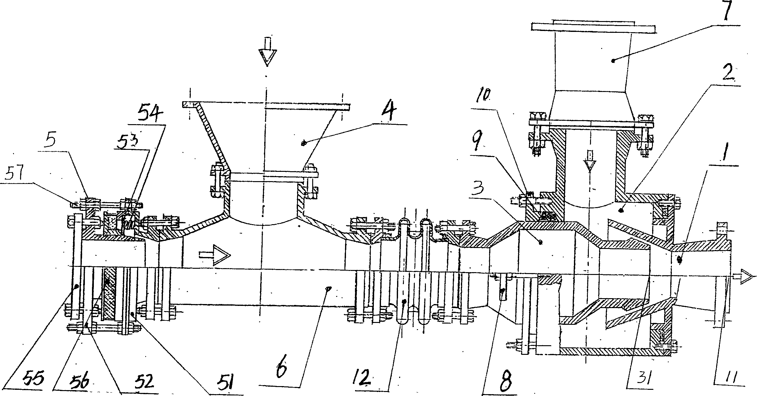
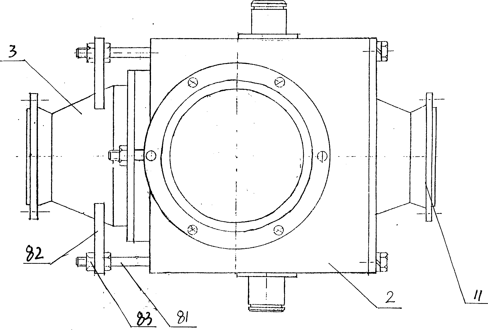
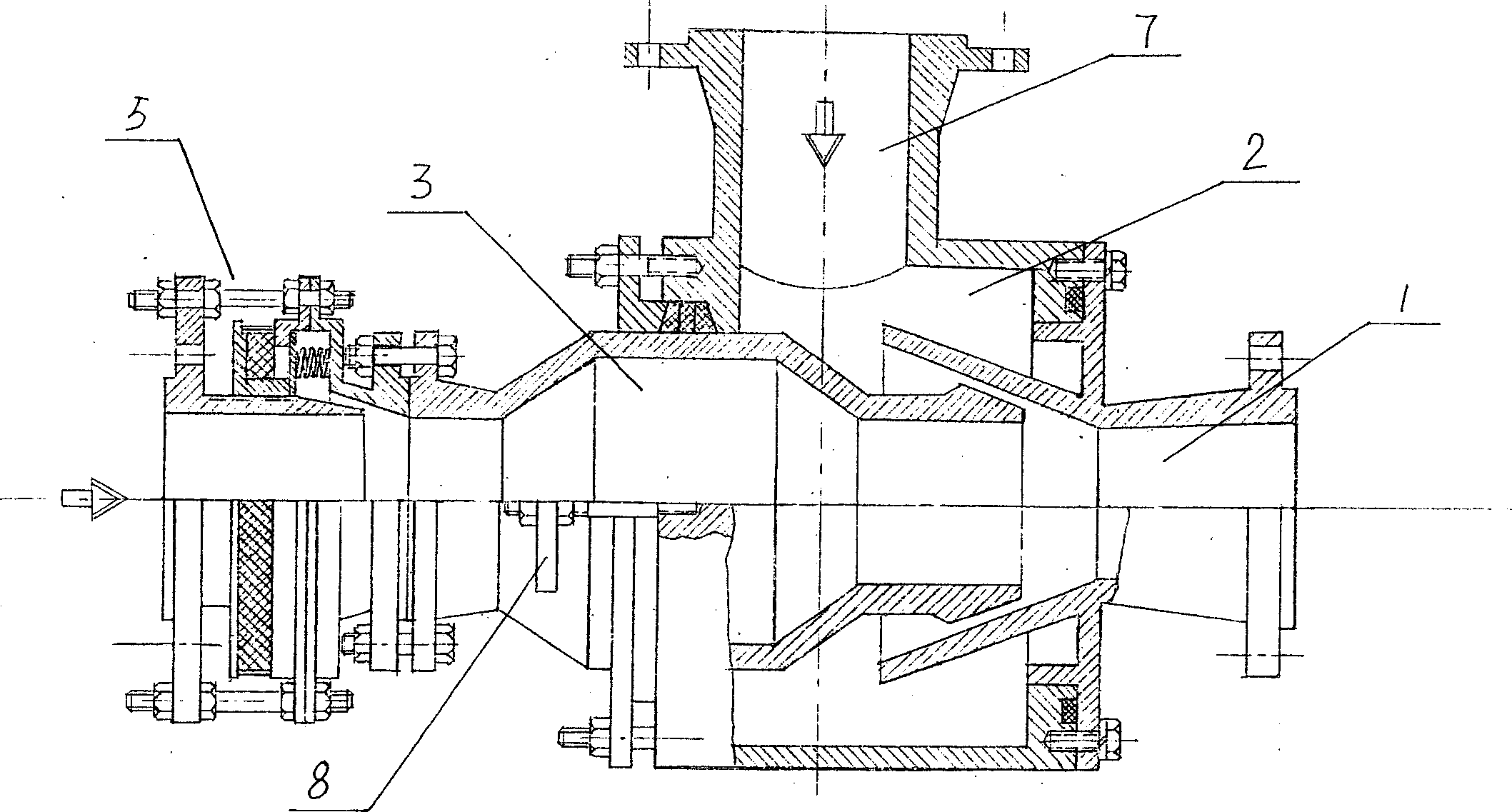
[0021] A conveying accelerator according to the present invention includes a mixing chamber 1 , a pressure chamber 2 , a suction chamber 3 , a feed port 4 and an air inlet device 5 . The mixing chamber 1 is trumpet-shaped and has a conical side wall. The mixing chamber 1 is sealed and fixed on one side of the pressure chamber 2 . The accelerator outlet 11 is formed at the narrowing of the conical surface of the mixing chamber 1 . The suction chamber 3 is hermetically installed on the other side of the pressure chamber 2. One end opening 31 of the suction chamber 3 extends into the conical side wall of the mixing chamber 1. The feed port 4 is connected to the air inlet device 5, and the telescopic tube 12 is used to connect the suction chamber 2 and the feed gas mixing tee 6, so that the position of the suction chamber opening 31 in the conical side wall of the mixing chamber 1 can be easily adjusted. Location. The sealed pressure chamber 2 is provided with a boosting inlet 7 ...

Embodiment 2

[0026] A conveying accelerator according to the present invention, in this embodiment, the feed inlet 4 in the present invention is closed, the air inlet device becomes the water inlet device 5 , and the suction chamber 3 is directly connected with the water inlet device 5 . For military industry, the present invention is placed on the bottom of the ship to replace the propeller, the water inlet device 5 faces to the front of the ship, and the accelerator outlet 11 faces to the rear of the ship. The supercharging equipment uses high-power multi-stage pumps to inject water, which generates high pressure in the pressure chamber 2, and the water flow in the water inlet device 5 is sucked, and a siphon phenomenon occurs between the mixing chamber, and the water flow is jetted through the accelerator outlet 11 to achieve high-speed propulsion, making the ship fly go ahead.


PUM


Abstract

A delivering accelerator based on the siphor phenomenon of fluid to generate high sucking force, push force and delivering power is composed of a mixing chamber with conic wall to form outlet of accelerator, a pressure chamber close to said mixing chamber, a sucking chamber installed at another side of pressure chamber in sealing mode, and the material inlet-gas inlet unit connected to sucking chamber via three-way. Said pressure chamber has also a boosting inlet connected to a booster and a regulator for regulating the output pressure of accelerator.

Description

1. Technical field [0001] The invention relates to a conveying device, in particular to a conveying accelerator. 2. Background technology [0002] With the continuous development of industrial society, people have higher and higher requirements for various conveying devices, especially in large-scale power plants, chemical industry, steel, mining and other enterprises, the pulverized coal input, pipeline transportation and loading and unloading of boilers are very important. link. At present, the pulverized coal conveying devices of the existing boilers all adopt the structure of fans and pipes. The disadvantages of this structure are: the transmission power is small, and the pulverized coal sent to the furnace is not uniform, and the combustion is insufficient, resulting in energy waste. In pipeline transportation, due to the longer distance to be transported, the use of fans cannot achieve the purpose. At present, there is no feasible transportation device for long-distan...

Claims


Application Information

Patent Timeline
Patent Type & Authority Applications(China)
IPC IPC(8): B65G53/58
Inventor 孙付江
Owner 孙付江
Why Eureka
Try Eureka