Supercharge Your Innovation With Domain-Expert AI Agents!

Plasma display panel and plasma display device

A plasma and display device technology, which is applied in the direction of AC plasma display panel, identification device, electrode configuration, etc., to achieve the effect of reducing cost, high luminous efficiency, and reducing holding discharge voltage

Inactive Publication Date: 2006-03-29
HITACHI LTD
View PDF7 Cites 0 Cited by
  • Summary
  • Abstract
  • Description
  • Claims
  • Application Information

AI Technical Summary

Problems solved by technology

Thus, there may be a case where a dielectric layer, a phosphor layer, and a rib are formed on the third electrode.

Method used


Image

  • Plasma display panel and plasma display device
  • Plasma display panel and plasma display device
  • Plasma display panel and plasma display device

Examples


Embodiment Construction

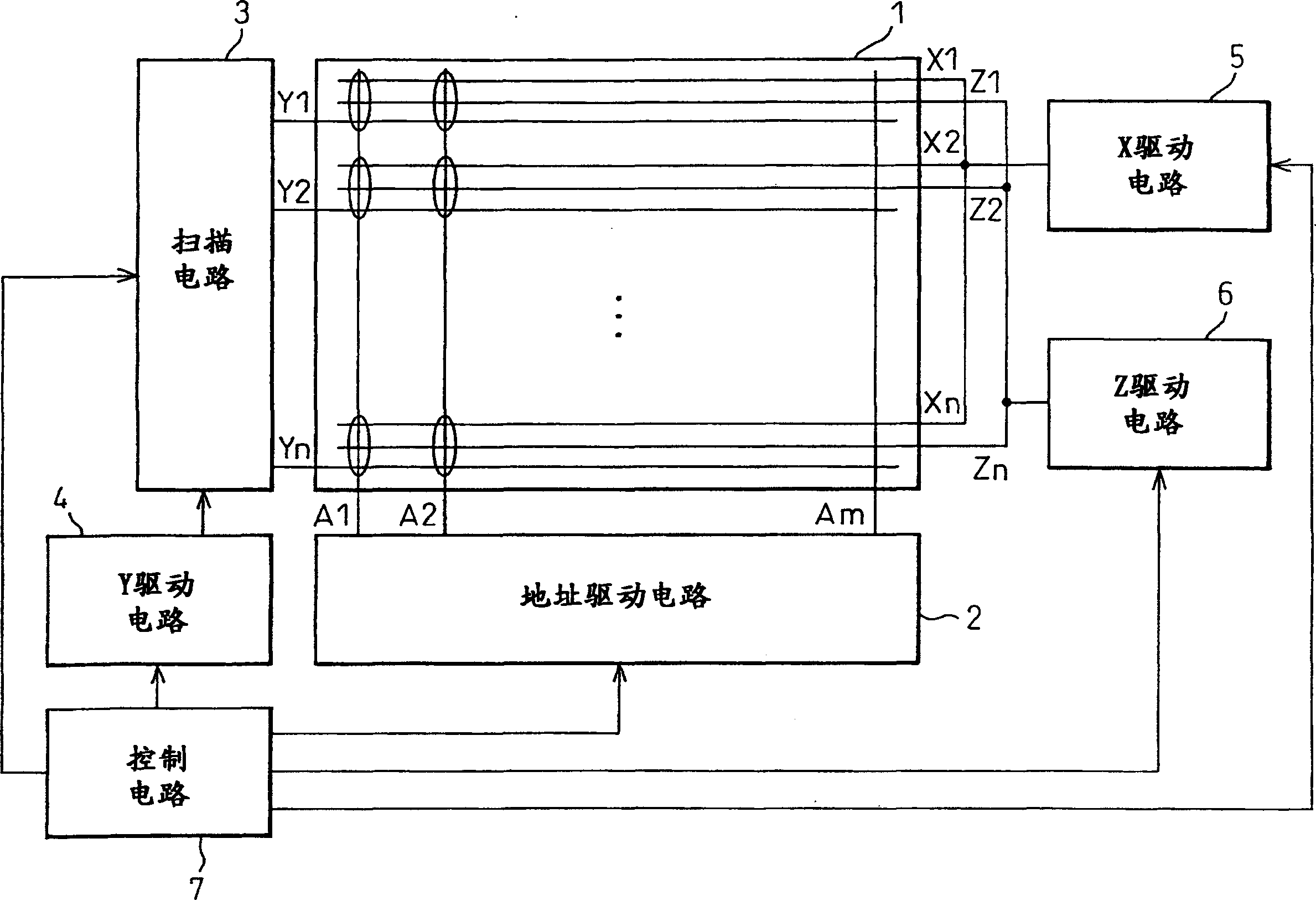
[0046] figure 1 This shows the overall structure of the plasma display device (PDP device) in the first embodiment of the present invention. The PDP1 used in the PDP device in the first embodiment is a conventional PDP in which a discharge occurs between the first (X) electrode and the second (Y) electrode pair, and the present invention is adopted. Such as figure 1 As shown in the PDP1 of the first embodiment, the X electrodes X1, X2,..., Xn and Y electrodes Y1, Y2,..., Yn that all extend laterally are alternately arranged, and each fourth electrode Z1 , Z2,..., Zn are arranged between each pair of X electrodes and Y electrodes. Thus, n three electrode groups are formed, namely X electrodes, Y electrodes and Z electrodes. In addition, address electrodes A1, A2,..., Am extending in the vertical direction are provided so as to intersect with the n groups of X electrodes, Y electrodes, and Z electrodes to form a unit at the intersection. Thus, n display rows and m display columns...


PUM


Abstract

A plasma display panel, the light emission efficiency of which has been improved without increasing the discharge start voltage, is disclosed. In a three-electrode type PDP, a fourth (Z) electrode is provided at the portion between a first (X) electrode and a second (Y) electrode between which a main discharge (a sustain discharge) is caused to occur for a display and at least one of the distance between the first electrode and the fourth electrode and the distance between the second electrode and the fourth electrode changes gradually in a cell.

Description

Technical field [0001] The present invention relates to an A / C type plasma display panel (PDP) and a plasma display device (PDP device) used as a display part of a personal computer or workstation, a flat TV or a plasma display used for displaying advertisements, information, etc. ). Background technique [0002] In AC-type color PDP devices, an address / display separation (ADS) system is widely used, in which the period for determining the cell to be displayed (address period) and the display period (hold period) for discharging the photoelectric element for display are Detached. In this system, during the address period, electric charge is accumulated in the cell to be lit, and during the sustain period, the electric charge is used to discharge and display. [0003] The plasma display panel includes a two-electrode type PDP in which a plurality of first electrodes extending in a first direction and parallel to each other are provided, and a plurality of second electrodes extendi...

Claims


Application Information

Patent Timeline
Patent Type & Authority Applications(China)
IPC IPC(8): H01J17/49H01J17/04H01J11/00H01J11/02G09F9/313H01J11/12H01J11/22H01J11/24H01J11/26H01J11/28H01J11/32H01J11/34
CPCH01J11/28H01J11/32H01J2211/323G09G2320/0228H01J2211/245G09G3/2986G09G2310/0218H01J11/12G09G3/294H01J11/22
Inventor 糸川直树小林敬幸佐佐木孝寺冈彻
Owner HITACHI LTD
Features
  • R&D
  • Intellectual Property
  • Life Sciences
  • Materials
  • Tech Scout
  • Unparalleled Data Quality
  • Higher Quality Content
  • 60% Fewer Hallucinations
Learn More