
Phase advance angle optimization for brushless motor control

A technology of phase advance and control system, which is applied in the field of phase lead angle optimization for controlling brushless permanent magnet motors, and can solve problems such as undercompensation, tracking performance degradation, and control strategy overcompensation

Inactive Publication Date: 2006-03-29
WAVECREST LAB LLC
View PDF6 Cites 22 Cited by
  • Summary
  • Abstract
  • Description
  • Claims
  • Application Information

AI Technical Summary

Problems solved by technology

The method of using lumped parameters often leads to the degradation of tracking performance, because the parameter value mismatch in each phase compensation procedure causes the control strategy to overcompensate or undercompensate

Method used


Image

  • Phase advance angle optimization for brushless motor control
  • Phase advance angle optimization for brushless motor control
  • Phase advance angle optimization for brushless motor control

Examples


Embodiment Construction

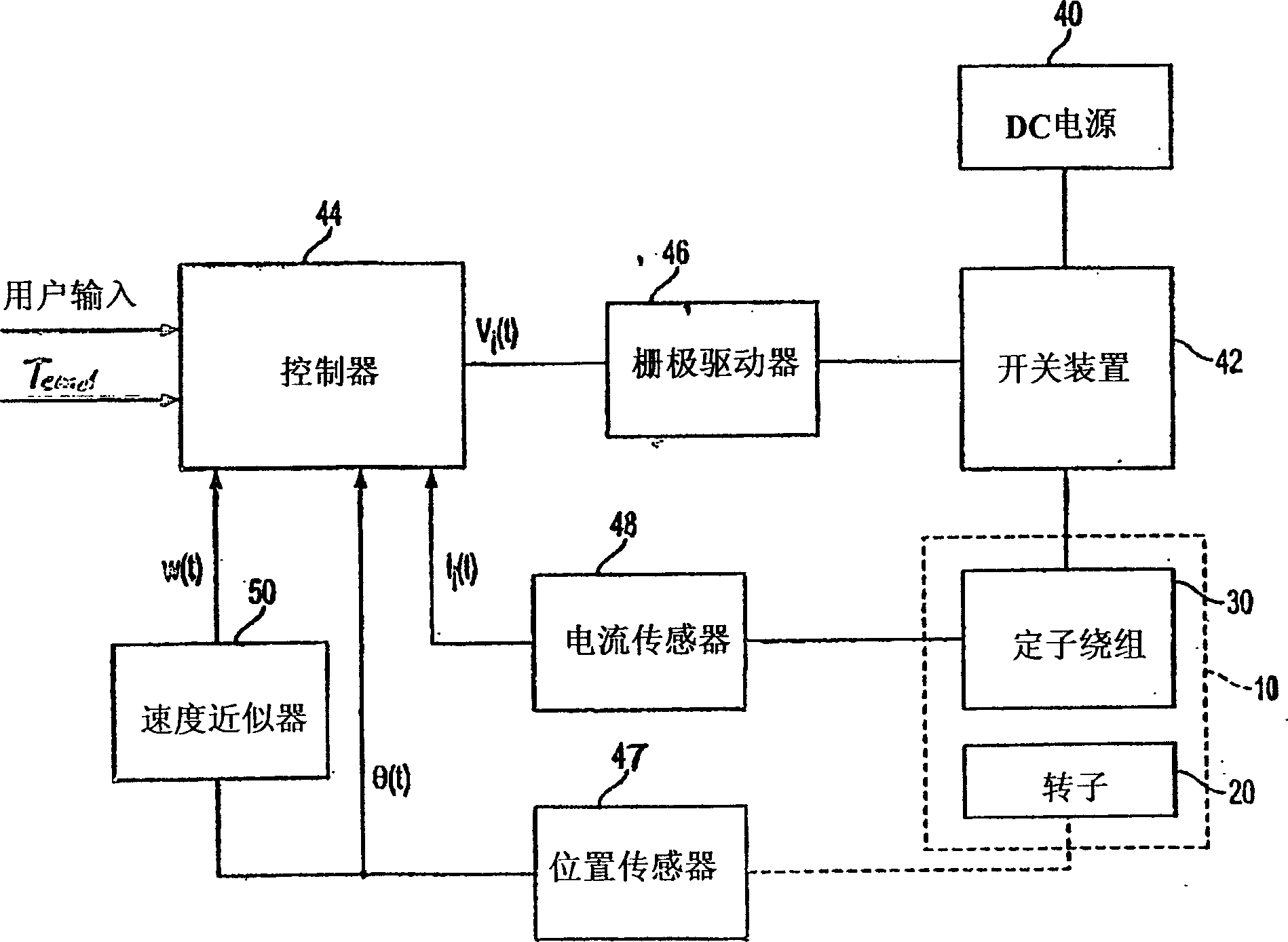
[0064] figure 2 is a block diagram of a motor control system according to the present invention. The multiphase electric machine 10 includes a rotor 20 and a stator 30 . The stator has a plurality of phase windings which are switchably energized by a drive current applied by a DC power supply 40 via an electronic switching device 42 . The switching device is connected to a controller 44 via a gate driver 46 . Controller 44 has one or more user inputs, and a plurality of inputs corresponding to motor conditions detected during operation. The current in each phase winding is sensed by a respective one of a plurality of current sensors 48 , the outputs of which are provided to the controller 44 . For this purpose, the controller may have multiple inputs, or alternatively, the signals from the current sensors may be multiplexed and connected to a single controller input. A rotor position sensor 47 is connected to another input of the controller 44 to provide a position signal...


PUM


Abstract

A control system for a multiphase permanent magnet motor having a controller for producing a control signal to energize each phase winding. The controller includes a current value calculator for determining a value of phase current advanced in phase with respect to back-EMF by a phase advance angle, and a phase advance optimization circuit for producing a value of the phase advance angle optimized so as to maximize output torque of the motor and mimimize the phase current. The phase advance optimization circuit determines the phase advance angle optimized for each phase of the motor.

Description

[0001] related application [0002] The subject matter of this application is related to the following pending U.S. application numbers: 09 / 826423 filed April 5, 2001 by Maslov et al., 09 filed April 5, 2001 by Maslov et al. / 826422, 09 / 966102 filed on October 1, 2001 by Maslov et al., 09 / 993596 filed on November 27, 2001 by Pyntikov et al., 10 / 173610 filed on June 19, 2002 by Maslov et al. All batch application numbers belong to this application in common. The disclosures of these applications are incorporated herein by reference. technical field [0003] The present invention relates to rotating electric machines, and more particularly, to a method for optimizing a phase lead angle for controlling a brushless permanent magnet electric machine. Background technique [0004] The pending application mentioned above describes the challenges of developing efficient motor drives. Electronically controlled pulsed excitation of motor windings offers the prospect of more flexibl...

Claims


Application Information

Patent Timeline
Patent Type & Authority Applications(China)
IPC IPC(8): H02P6/18H02P6/14H02K23/16
CPCH02P6/142H02P6/15H02P6/18
Inventor 鲍里斯·A·马斯洛夫马修·G·菲姆斯特袁国辉
Owner WAVECREST LAB LLC
Learn More