Ellipse track machine

An elliptical machine and pedestal technology, applied in the field of elliptical machines, can solve the problems of pulling the hamstrings, volleying the heels, and feeling fatigued on both feet.

Inactive Publication Date: 2006-04-05
JOHNSON HEALTH TECH
View PDF0 Cites 14 Cited by
  • Summary
  • Abstract
  • Description
  • Claims
  • Application Information

AI Technical Summary

Problems solved by technology

[0004] Because these pedals 15 are fixed on the top surfaces of these pedal shafts 14 in a fixed manner, and cannot change the positioning angle with these pedal shafts 14, therefore, when these pedal shafts 14 follow the elliptical trajectory movement, will Because of the change of the angle, different inclination angles are produced, so that the pedals 15 are inclined with the inclination of the pedal shafts 14, so, in the process of exercise, the pedals 15 cannot provide the user's feet all the way. A stable support effect causes part of the motion stroke, especially when the pedal shafts 14 advance to the upper and lower poles, the heel will be lifted and the situation in the air will be raised. In this case, the user is easy to move. During the process, the hamstrings may be pulled, making the feet prone to fatigue and unable to carry out long-term exercise

Method used


Image

  • Ellipse track machine
  • Ellipse track machine
  • Ellipse track machine

Examples


Embodiment Construction

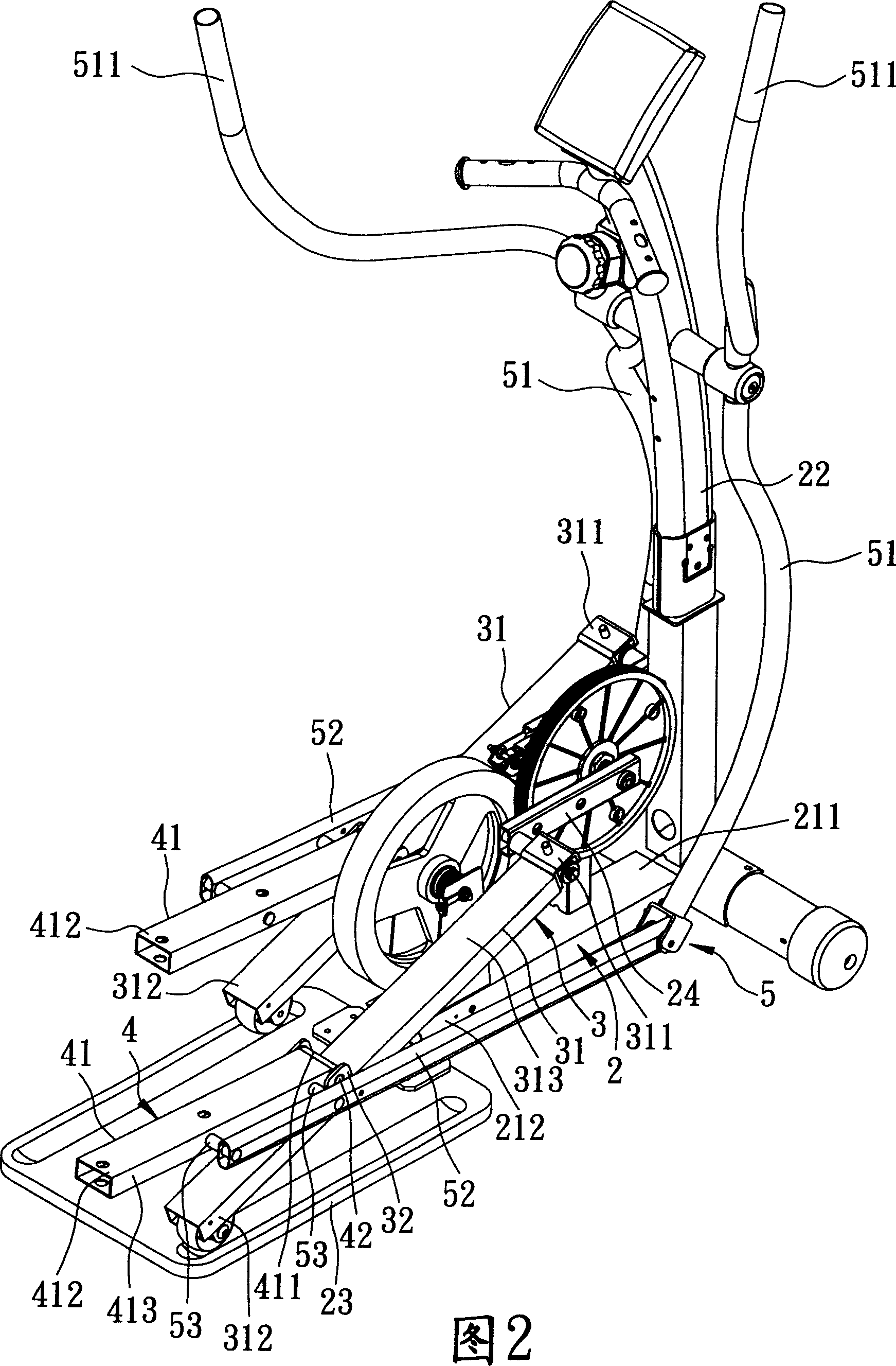
[0016] See Figure 2, image 3 , Figure 4 , The preferred embodiment of the elliptical machine of the present invention includes a body 2 , two sliding components 3 , two pedal components 4 and two linkage components 5 .

[0017] The body 2 has a base 21, an instrument panel frame 22 standing on a front end 211 of the base 21, a rail seat 23 formed on a rear end 212 of the base 21, and a rotatable frame. Two cranks 24 are placed on the base 21 and adjacent to the front end 211 of the base 21 .

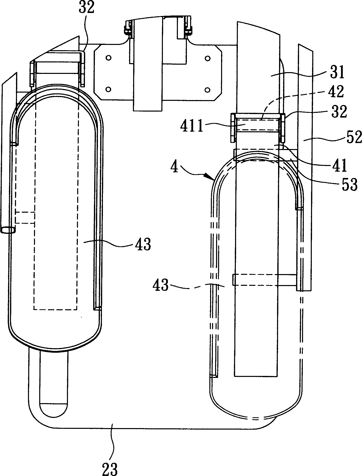
[0018] The sliding components 3 respectively have a sliding rod 31 and a U-shaped ear seat 32 . A front end 311 of the sliding rod 31 is pivotally connected with the crank 24 to form interlocking movement, and a rear end 312 slides on the rail seat 23 . The U-shaped ear seat 32 is formed on a top surface 313 of the sliding bar 31 and adjacent to the rear end 312 .

[0019] The pedal assemblies 4 respectively have a step 41 , a pivot 42 and a pedal 43 . The step 41 is inserted betwe...


PUM


Abstract

The invention discloses an elliptical machine, comprising: a body, two sliding components with an elliptical path of movement built on the body, two pedal components which can pitch float on the sliding component, and two linkage units that can connect the body and the pedal with fore-and-aft moving. The linkage unit can draw the pedal to float in the motivation when the pedal component moves along the elliptical path of movement, which makes the foot movement coincident with the human engineering.

Description

technical field [0001] The invention relates to an elliptical machine, in particular to an elliptical machine whose pedals can be pitched and swung to conform to ergonomics. Background technique [0002] Referring to Fig. 1, taking the Taiwan Publication No. 578578 patent case as an example, the elliptical exercise machine 1 mainly includes: a base 11, an instrument panel frame 12 standing on a front end 111 of the base 11, a rotatable The two cranks 13 mounted on the base 11 and adjacent to the front end 111, the two pedal shafts 14 pivotally connected to the cranks 13 and sliding on the rear end 112 of the base 11, are respectively fixed on the Two pedals 15 on the pedal shafts 14 , two swing arms 16 pivotally connected to the dashboard frame 12 respectively, and two connecting rods 17 pivotally connected to the swing arms 16 and connected to the pedals 15 respectively. [0003] In this way, the user only needs to stand on the pedals 15, respectively apply a forward and b...

Claims


Application Information

Patent Timeline
Patent Type & Authority Applications(China)
IPC IPC(8): A63B22/04
Inventor 廖宏茂黄得彰
Owner JOHNSON HEALTH TECH
Why Eureka
Try Eureka