Compressor impeller structure

A compressor blade and blade technology, which is applied in mechanical equipment, machines/engines, liquid fuel engines, etc., can solve the problems of unsmooth operation of blades 40, shortened parts life, friction noise, etc., so as to improve reliability, prevent noise, Anti-friction effect

Inactive Publication Date: 2006-04-05
LG ELECTRONICS (TIANJIN) APPLIANCES CO LTD
View PDF0 Cites 2 Cited by
  • Summary
  • Abstract
  • Description
  • Claims
  • Application Information

AI Technical Summary

Problems solved by technology

Therefore, the operation of the blade 40 is not smooth, and wear between the wave surface of the isolation plate 30 and the co

Method used


Image

  • Compressor impeller structure
  • Compressor impeller structure
  • Compressor impeller structure

Examples


Embodiment Construction

[0027] With reference to accompanying drawing, describe in detail about the blade structure of compressor of the present invention as follows:

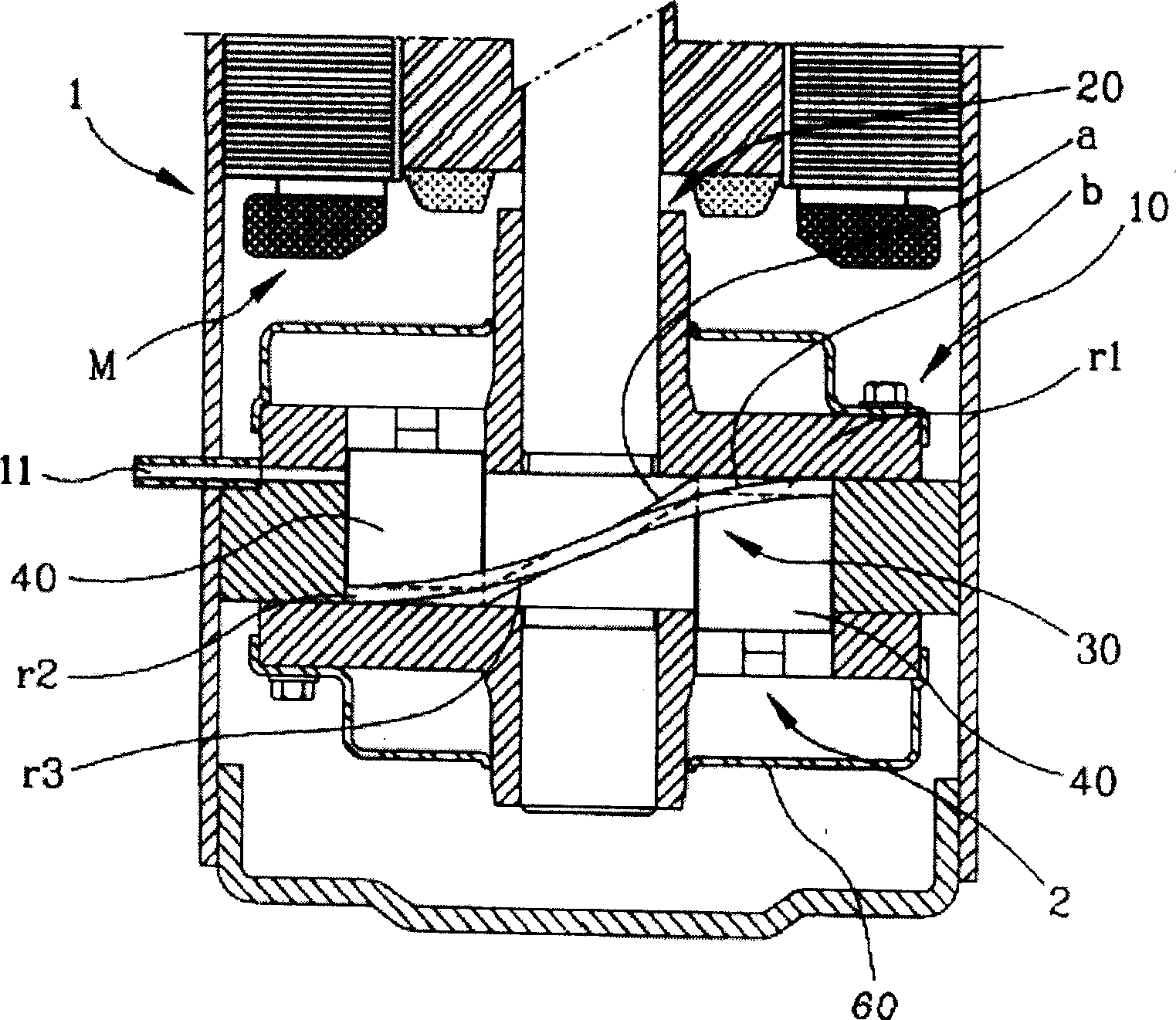
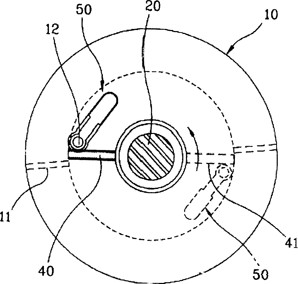
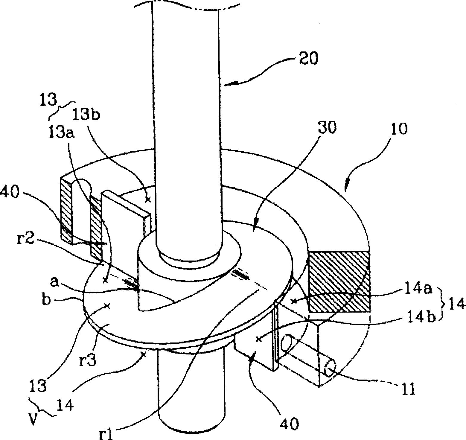
[0028] Figure 5 , 6 is an illustration of a compression mechanism part of a compressor showing the compressor blade structure of the present invention. It includes a cylinder assembly 10 with an internal space V and a suction flow path 11 communicating with the internal space V and a discharge flow path (not shown); The rotating shaft 20; the internal space V of the cylinder assembly 10 is rotatably connected with the rotating shaft 20 and isolates the internal space V into the first and second space 13, 14 isolation plate 30; Spaces 13 and 14 are inserted into the above-mentioned cylinder assembly 10 in contact with the isolation plate 30 and perform linear reciprocating motion in the axial direction with the rotation of the rotating shaft 20. The above-mentioned first space 13 and second space 14 are respectively converted into su...


PUM


Abstract

The invention discloses a compressor blade structure, wherein the compressor comprises the following parts: cylinder component with inner space; rotary axle through inner space inserted in the cylinder component; segregation barrier of rotary plug-in function connects rotary axle for segregating the inner space; blade changes the segregated space into intake domain and works linear round-trip movement along the rotary axle of cylinder component; The blade contains certain thickness and area, whose two sides touch the outer rotary axle surface and inner cylinder component separately and plug in the blade parent body plate whose one side is set a rotary plug-in roller to touch segregation barrier line. The invention can move the blade more slippery because of little fiction between blade and segregation barrier, which reduces the noise and lengthen the component lifespan to improve the production reliability.

Description

technical field [0001] The present invention relates to the invention of the compressor blade structure, especially the invention of the compressor blade structure which minimizes the friction during operation and makes the operation smooth. Background technique [0002] Generally, a compressor is a machine that compresses gas. The structure of such a compressor is composed of a closed container with a certain space, a motor mechanism part installed inside the closed container and generating a driving force, and a compression mechanism part that compresses gas by receiving the driving force of the motor part. There are many forms. [0003] Korean Patent No. 99-42381 of the author of the present invention discloses an invention of a compressor having a different compression method from the original compressor. figure 1 , 2, 3 are the presentation diagrams of the compression mechanism part of the original compressor that uses the driving force of the motor mechanism part to ...

Claims


Application Information

Patent Timeline
IPC IPC(8): F04C29/00F04C18/00
Inventor 沈再术金永宗安丙河
Owner LG ELECTRONICS (TIANJIN) APPLIANCES CO LTD
Why Eureka
Try Eureka