Pneumatic instrument for measuring outside diameter of thin-wall bearing

A technology of pneumatic measuring instrument and thin-walled bearing, which is used in mechanical bearing testing, measuring devices, instruments, etc., to achieve the effect of long service life, convenient operation and simple overall structure

Inactive Publication Date: 2006-04-05
LUOYANG BEARING GROUP
View PDF0 Cites 9 Cited by
  • Summary
  • Abstract
  • Description
  • Claims
  • Application Information

AI Technical Summary

Problems solved by technology

There is currently no effective way to measure this

Method used


Image

  • Pneumatic instrument for measuring outside diameter of thin-wall bearing
  • Pneumatic instrument for measuring outside diameter of thin-wall bearing

Examples


Embodiment Construction

[0028] Specific embodiments of the present invention are described with reference to the accompanying drawings.

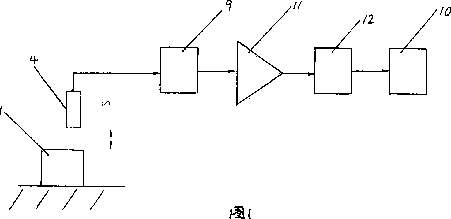
[0029] As shown in FIG. 1, the present invention mainly includes a gas-electric converter 9 (existing), an electronic display 10 (existing) and a pneumatic probe 4. The pneumatic probe 4 adopts a circular structure and is placed on a measuring device , there are eight or more even-numbered measuring nozzles 3 (8 measuring nozzles are used in this implementation) evenly distributed in the circumferential direction of the probe, which is to spray the compressed air through the nozzle 3 to the outer diameter of the bearing ring 1 placed inside it , the pneumatic probe 4 changes the airflow pressure into the change of the length value according to the induction, converts it through the pneumatic-electric converter 9, and makes the electronic display 10 display the measured value through the amplifier 11 and the drive circuit 12.

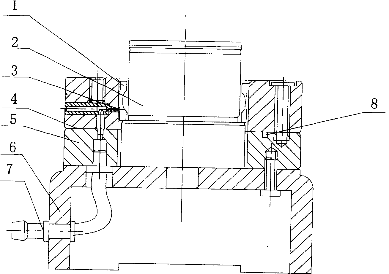
[0030] like figure 2 As shown, the me...


PUM


Abstract

The invention discloses a thin wall bearing ring optical density air gauge, which comprises an electric translator (10), an electric display (11) and air measurer(4) which adopts a ring structure and is arranged on a measuring device; it inlets the condensed air through the grouter of the air measurer into the inner bearing ring(1)optical density, the air measurer(4) can use the electric translator (10) to change and use the electric display (11) to display the measuring value by the change of the length value of the draft force.

Description

Technical field [0001] The invention belongs to a bearing outer diameter measuring device, and mainly relates to a small and medium-sized thin-walled bearing ring outer diameter pneumatic measuring instrument. Background technique: [0002] At present, the thinnest wall thickness of small and medium-sized bearing rings is only 0.275mm, and the size and shape and position tolerance of thin-walled bearing rings are easily deformed when measured by traditional mechanical measuring instruments, which cannot be effectively measured; and due to the measurement force (usually 120~200g), the measured surface is easy to produce test marks, which affects the surface quality of the measured workpiece. This problem is a major problem in the bearing processing and even the machinery industry. Especially in the production process of military bearing rings, the impact is particularly prominent, which has special technical requirements for flexible bearing rings: control the average value o...

Claims


Application Information

Patent Timeline
Patent Type & Authority Applications(China)
IPC IPC(8): G01B13/08G01M13/04
Inventor 王景夏孙金花刘桥方乔卫红张远
Owner LUOYANG BEARING GROUP
Why Eureka
Try Eureka