Shift locking device for transmission
A technology of locking device and transmission, applied in the direction of transmission control, components with teeth, belt/chain/gear, etc., to achieve the effect of preventing automatic shifting
- Summary
- Abstract
- Description
- Claims
- Application Information
AI Technical Summary
Problems solved by technology
Method used
Image
Examples
Embodiment 1
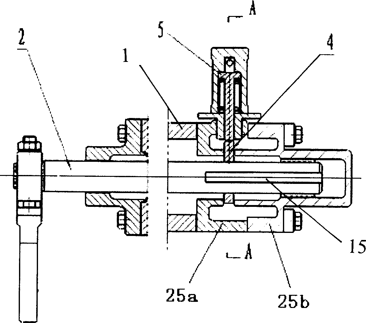
[0022] The gear locking mechanism of the transmission in this embodiment includes a telescopic locking mechanism 5 fixed on the gearbox body 1 and a shift shaft 2 with a limit linkage mechanism. The telescopic locking mechanism 5 cooperates with the limit linkage mechanism to realize switching Locking of gear shaft. see figure 1 .
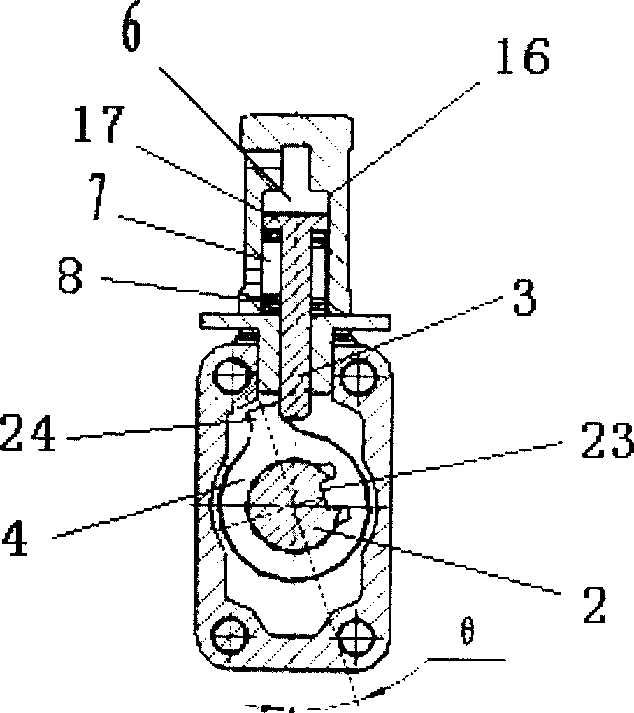
[0023] The retractable locking pin mechanism 5 includes a locking pin 3 , a return spring 8 and a pneumatic cylinder 16 connected with the locking pin 3 . Wherein, the cylinder body of the pneumatic cylinder 16 is fixed on the gearbox body 1; the lock pin 3 is connected with the lower end of the piston 17 of the pneumatic cylinder 16 as a whole, the upper chamber of the pneumatic cylinder 16 is the locking chamber 6, and the lower chamber of the pneumatic cylinder is the return chamber. A position air chamber 7 and a return spring 8 are installed in the return air chamber 7, and the pneumatic cylinder 16 communicates with the pressure air source ...
Embodiment 2
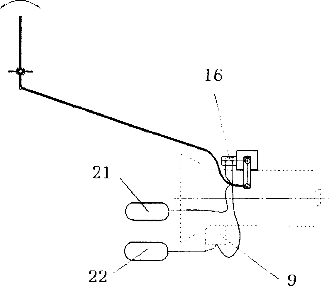
[0033] see Figure 4 , figure 2 , the difference between this embodiment and Embodiment 1 is that the pressure air source control system includes an air storage tank 21 and a two-position four-way solenoid valve 12, the solenoid valve control switch 11 is linked with the clutch pedal; the air storage tank 21 passes through the pipeline The two-position four-way solenoid valve is connected with the pneumatic cylinder 16, and the delay disconnection trigger 13 is connected in series between the electric control end of the solenoid valve and the control switch 11. Release the clutch pedal, the control switch is disconnected, the solenoid valve returns, the air storage tank 21 is connected to the locking chamber 6 of the pneumatic cylinder, the returning air chamber 7 is exhausted, and the lock pin 3 is stretched out at the locking position; step on the clutch Pedal, the control switch is closed, the solenoid valve shifts and changes direction, the air storage tank 21 is connect...
PUM
 Abstract
Description
Claims
Application Information
 - R&D
- Intellectual Property
- Life Sciences
- Materials
- Tech Scout
- Unparalleled Data Quality
- Higher Quality Content
- 60% Fewer Hallucinations
Browse by: Latest US Patents, China's latest patents, Technical Efficacy Thesaurus, Application Domain, Technology Topic, Popular Technical Reports.
© 2025 PatSnap. All rights reserved.Legal|Privacy policy|Modern Slavery Act Transparency Statement|Sitemap|About US| Contact US: help@patsnap.com


