Cathode ray tube

A cathode ray tube and shadow mask technology is applied in the field of improving the curved surface retention strength of the shadow mask, and can solve the problems of reducing image quality and the like

Inactive Publication Date: 2006-04-26
MATSUSHITA TOSHIBA PICTURE DIS
View PDF0 Cites 2 Cited by
  • Summary
  • Abstract
  • Description
  • Claims
  • Application Information

AI Technical Summary

Problems solved by technology

[0011] However, when attempting to obtain sufficient curved surface holding strength to provide a reinforcing bead to an active surface having a large radius of curvature, the spacing between the active surface of the shadow mask and the inner surface of the active portion of the panel deviates locally from the allowable range , a stepwise (step) image is displayed on the screen due to the provision of this reinforcement bead, and this significantly reduces the image quality
Thus, the height of the reinforcement bead is typically limited to only about 0.2 mm, which in turn limits the amount by which the surface retention strength can be improved

Method used


Image

  • Cathode ray tube
  • Cathode ray tube
  • Cathode ray tube

Examples


Embodiment Construction

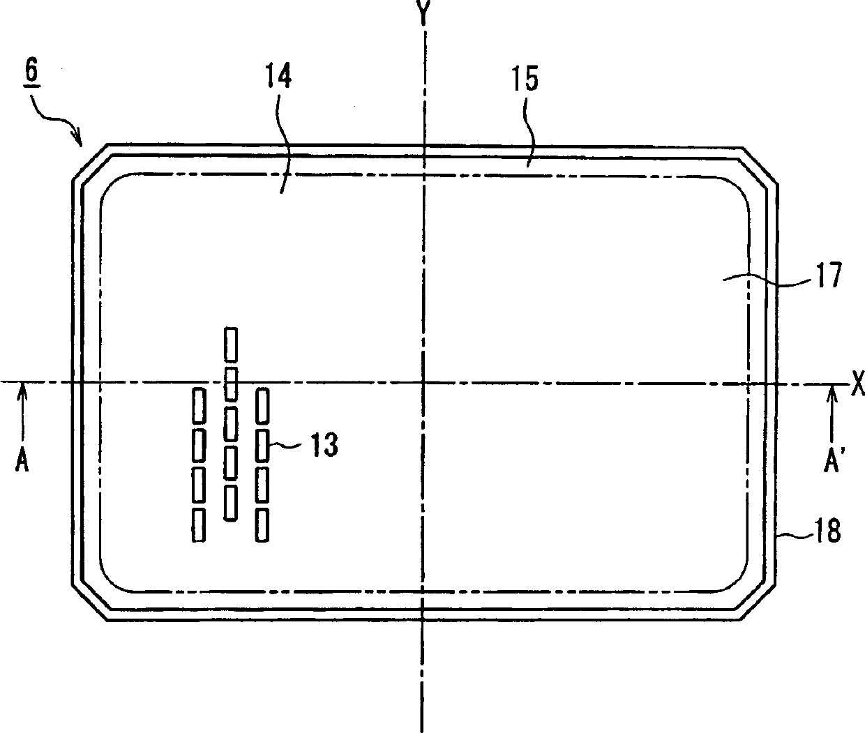
[0025] By satisfying the several formulas of the present invention given above, it is possible to increase the curved surface holding strength of the shadow mask main body, thereby reducing the deviation of electron beam landing and preventing the degradation of color purity.

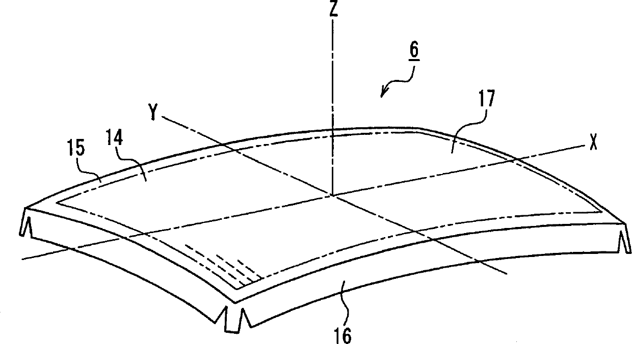
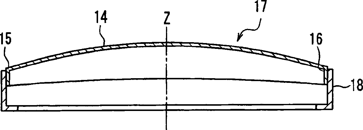
[0026] In the present invention, it is preferred that the effective surface has the horizontal axis as one side thereof and the 30 mm wide band-shaped range extending from the horizontal axis end point to the tube axis side includes a portion in which the radius of curvature of the effective surface in the vertical axis direction is The distribution is a concave radius of curvature distribution with a minimum value.

[0027] In addition, it is preferable that the effective surface has the horizontal axis as its one side and the 30mm-width band-shaped range extending from the horizontal axis end point to the pipe axis side includes a portion in which the effective surface has a distribution of curvature r...


PUM


Abstract

The shadow mask main body 17 includes an effective surface 14 in which electron beam passage holes 13 are formed and a non-porous portion 15 surrounding the effective surface 14 . When we let Ry be the curvature radius of the curve on the Y-axis direction of the effective surface 14 of the shadow mask main body 17, and Rx be the curvature radius of the curve on the X-axis direction, calculate the curvature radius of the curved surface on the effective surface 14 with Rk2=Rx×Ry Rk, and let Rk(d) be the radius of curvature of the curved surface near the endpoint of the diagonal axis of the effective surface 14, Rk(h) be the radius of curvature of the curved surface near the X-axis endpoint, and Rk(c) be the curvature of the curved surface in the middle portion When the radius is used, the following relationships are satisfied: Rk(c)>Rk(h), Rk(c)>Rk(d) and -800mm≤Rk(h)-Rk(d)≤800mm.

Description

technical field [0001] The present invention relates to a cathode ray tube using a shadow mask, and more particularly to a technique for increasing the curved surface retention strength of the shadow mask. Background technique [0002] Fig. 10 is a cross-sectional view of an example of a conventional cathode ray tube. The cathode ray tube 1 includes a vacuum envelope 2 , various components attached to the vacuum envelope 2 , and a deflection device 12 provided around the outer surface of the vacuum envelope 2 . The vacuum envelope 2 is formed by connecting a funnel-shaped funnel 4 and a panel 3 together. The panel 3 includes a side wall portion 3b that surrounds the effective portion 3a formed as a curved surface, and the funnel 4 is connected to the side wall portion 3b. A fluorescent screen 5 is provided on the inner surface of the effective portion 3 a of the panel 3 . The fluorescent screen 5 is formed of a black non-luminous layer and three color light-emitting layer...

Claims


Application Information

Patent Timeline
Patent Type & Authority Applications(China)
IPC IPC(8): H01J29/07
CPCH01J29/07H01J2229/0788H01J2229/0794
Inventor 增村哲哉
Owner MATSUSHITA TOSHIBA PICTURE DIS
Why Eureka
Try Eureka