Vibrating slab tamper

A plate compaction and vibrating shaft technology, which is applied in the field of machines, tools or auxiliary equipment, can solve the problems of fast compaction, injury, and low productivity, and achieve the effects of avoiding unsafe accidents, improving production efficiency, and reducing production costs

Inactive Publication Date: 2006-05-03
CHANGAN UNIV
View PDF0 Cites 6 Cited by
  • Summary
  • Abstract
  • Description
  • Claims
  • Application Information

AI Technical Summary

Problems solved by technology

The main disadvantage of the frog-type ramming machine is that the ramming effect is poor, which can no longer meet the requirements of use. It is required that the thickness of the paved soil layer cannot be deep, and the productivity is not high. The stress-bearing parts often break, and the connecting bolts on the tamp head frame are easy to loosen under continuous impact. If they are not checked frequently, the eccentric block will fly out and cause accidents such as injury. During the construction process, the noise is loud, Especially construction in residential areas has become a well-known public hazard
In addition, the frog-type ramming machine has a high labor intensity for the operator during use, and the transmission belt 15 is prone to failure due to the periodic change of the exciting force of the eccentric block, and needs to be replaced frequently, and disassembly and assembly are more troublesome
[0003] At present, the vibratory plate compactor used on the construction site uses two vibrating shaft exciters, and the two vibrating shafts rotate in reverse, which limits the power of the vibratory plate compactor.
Most of the structural settings are that the eccentric excitation device is arranged at the front of the complete machine, and the power device is arranged at the rear of the complete machine. The weight of the power device is greater than the weight of the eccentric excitation device, which is likely to cause uneven weight distribution of the complete machine in terms of structural settings. Even, resulting in uneven compaction
[0004] Impact rammers, one-way vibratory plate compactors and two-way plate compactors produced in the United States are large in size, fast in compaction speed, and high in compaction efficiency. These compactors can only compact large-area foundations. Work cannot be done in smaller tunnels, and these rammers are expensive to sell

Method used


Image

  • Vibrating slab tamper
  • Vibrating slab tamper
  • Vibrating slab tamper

Examples


Embodiment 1

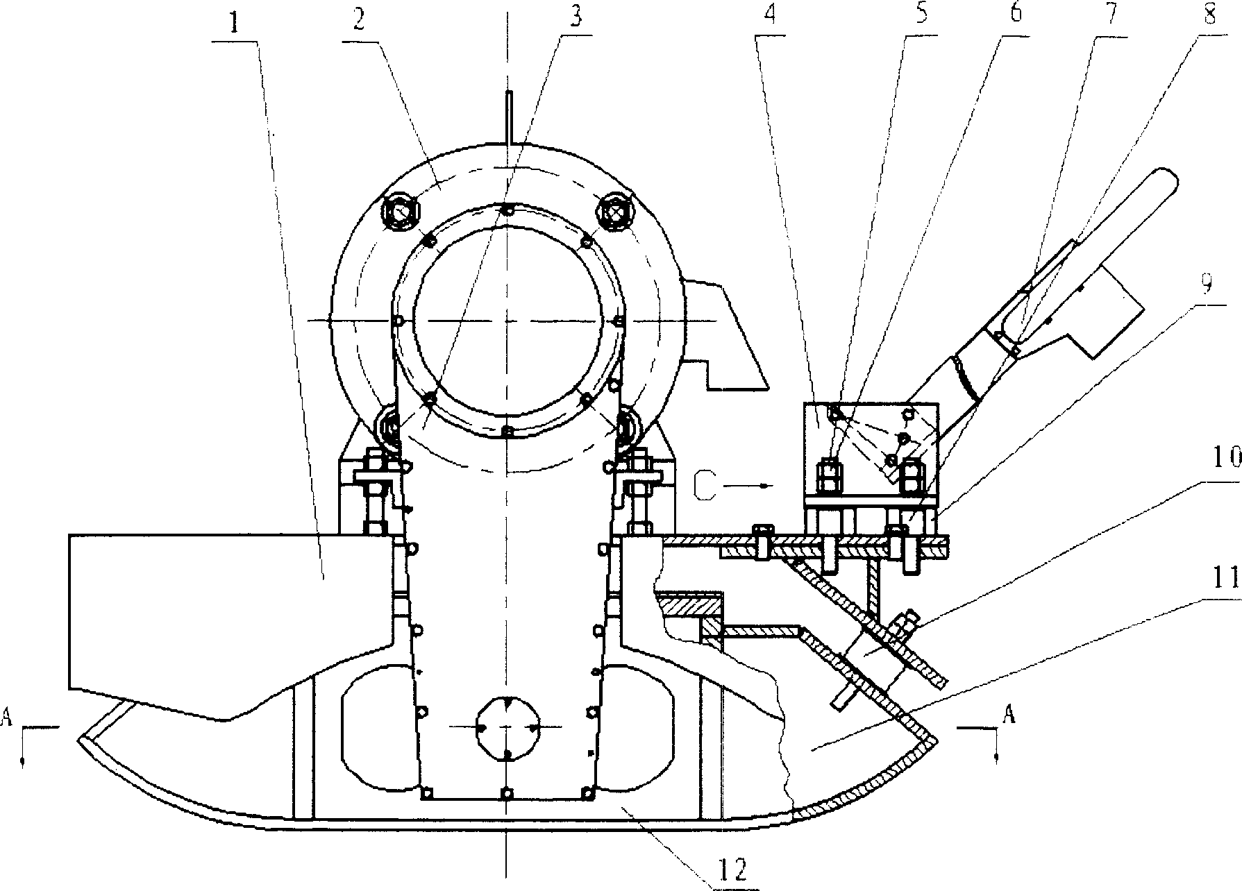
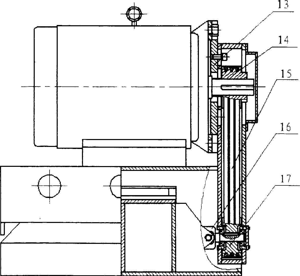
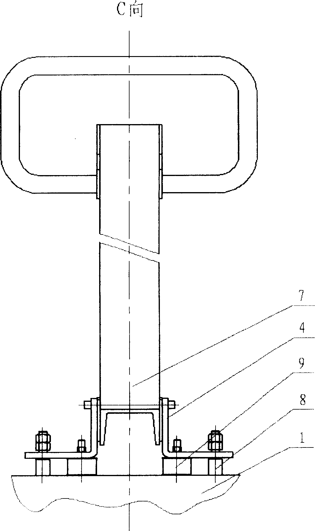
[0027] exist figure 1 , 2 , 3, 4, the vibrating plate compactor of the present embodiment is made of mounting plate 1, motor 2, pulley box 3, handrail seat 4, screw rod 5, nut 6, handrail 7, screw rod mounting seat 8, handrail rubber vibration damping on the frame Block 9, rubber damping block 10, frame lower mounting plate 11, loading mechanism 12, mounting flange 13, driving wheel 14, belt 15, universal joint 16, driven wheel 17 are connected and formed.

[0028] On the mounting plate 1 on the frame, a motor 2 is fixedly connected with a threaded fastening joint, and a mounting flange 13 is fixedly connected with a threaded fastening joint on the motor 2, and a threaded fastening joint is used on the lower mounting plate 11 of the frame. A loading mechanism 12 is fixedly connected, and an armrest seat 4 is fixedly connected to the mounting plate 1 on the frame with a threaded fastening joint, and an armrest is fixedly connected between the armrest seat 4 and the mounting pl...


PUM


Abstract

The invention discloses a vibration flat rammer, which is characterized by the following: setting motor on the frame and armrest on the armrest seat; fixing flange on the motor; setting arm seat absorber and absorber protector between armrest seat and upper installment plate; fixing the loading system on the rack lower installment plate; setting pulley box with driving structure in connection with the motor and loading system on the installment flange; adapting front eccentric block, middle eccentric block and back eccentric block in the loading case to generate exciting force to compact ground foundation through motor driving system; setting lubrication system in the loading case to lubricate the operation part and reduce noise. The invention adapts universal joint as driving part, which avoids the rigidity driving shaft breakdown phenomenon.

Description

technical field [0001] The invention belongs to the technical field of paving and repairing machines, tools or auxiliary equipment for pavement of roads or other similar structures, and in particular relates to vibratory flat compactors. Background technique [0002] At present, in the compaction of narrow areas in construction projects, the frog type ramming machine developed in the 1960s is still widely used, and its structure is simple and the production cost is low. The main disadvantage of the frog-type ramming machine is that the ramming effect is poor, which can no longer meet the requirements of use. It is required that the thickness of the paved soil layer cannot be deep, and the productivity is not high. The stress-bearing parts often break, and the connecting bolts on the tamp head frame are easy to loosen under continuous impact. If they are not checked frequently, the eccentric block will fly out and cause accidents such as injury. During the construction proces...

Claims


Application Information

Patent Timeline
Patent Type & Authority Applications(China)
IPC IPC(8): E01C19/38E01C19/35
Inventor 郁录平吕彭民高彦军欧阳颖谢军
Owner CHANGAN UNIV
Why Eureka
Try Eureka