
Backlight assembly and its lamp activating method

A technology for backlight components and lamps, applied in optics, discharge lamps, electrical components, etc., can solve problems such as transformer burnout, inability to light all lamps at the same time, and reduced product reliability.

Inactive Publication Date: 2006-05-03
DELTA ELECTRONICS INC
View PDF0 Cites 0 Cited by
  • Summary
  • Abstract
  • Description
  • Claims
  • Application Information

AI Technical Summary

Problems solved by technology

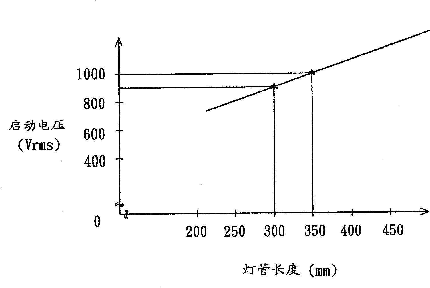
However, the current design of transformers for the activation voltage has reached more than 1,000 volts. If the activation voltage continues to increase and the voltage of the transformer is continuously increased, it will cause a large increase in production costs and a decrease in product reliability.
Because the higher the activation voltage is, the more difficult it is to make the transformer. Not only the winding ratio of the transformer increases, but also the high-voltage resistance of the material must also be increased. Otherwise, the transformer is prone to flashover due to poor insulation, which will cause the transformer to burn out.
In addition, due to the slight difference in the impedance of different lamp tubes, when multiple lamp tubes are lit at the same time, this difference will cause the problem that all the lamp tubes cannot be lit at the same time
[0006] The second is to coat substances such as cesium on the inner wall of the lamp tube or on the electrodes. However, since cesium and other substances are toxic substances, once the lamp tube fails to be discarded, the cesium and other substances coated on the inner wall of the lamp tube will cause environmental damage. Therefore, this method not only causes environmental pollution, but also adds a coating step to the manufacturing process, which is more labor-intensive and is not an ideal solution.

Method used


Image

  • Backlight assembly and its lamp activating method
  • Backlight assembly and its lamp activating method
  • Backlight assembly and its lamp activating method

Examples


Embodiment Construction

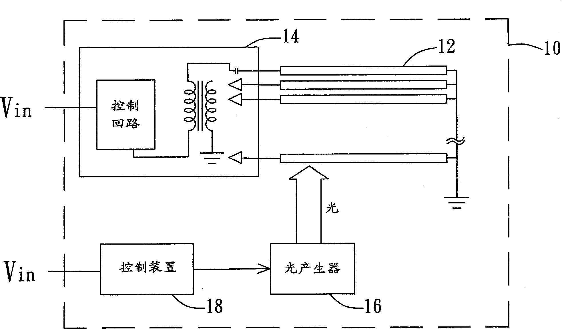
[0015] Please refer to figure 1 , which is a schematic diagram of the backlight assembly of the present invention. A backlight module 10 disclosed in a preferred embodiment of the present invention includes at least one light tube 12 , a regulating component 14 and a light generator 16 . The plurality of lamps 12 are cold cathode fluorescent lamps (Cold Cathode Fluorescent Lamp, CCFL), arranged in parallel, and electrically connected with the regulating component 14 . The regulating component 14 includes a transformer and a control circuit. The transformer can convert a voltage from an external power source and output an activation voltage to the lamp 12. The control circuit is electrically connected to the transformer to control the voltage output by the transformer. In this way, the externally input voltage, such as a commercial power (AC), can be converted by the control component 14 to output a usable voltage for the lamp tube 12 , such as a direct current (DC).

[0016]...


PUM


Abstract

The invention relates to a negative phototropic component and a tube acting method. The negative phototropic component comprises at least one tube and a light generator. The light generator can generate light energy to promote part of the electron free inside the tube, so that we input the acting voltage below the tube bur to active the tube. The tube is electric connected with a regulate-controlling assemble to control the output voltage to the tube after converting. The regulate-controlling assemble comprises a converter and a control circuit, wherein the converter can convert a voltage from the out power and output to control the electric connection between the control circuit and the converter and the outputted voltage size of the converter.

Description

technical field [0001] The invention relates to a backlight assembly and a lamp tube activation method thereof, in particular to a high-efficiency backlight assembly and a lamp tube activation method thereof. Background technique [0002] Cold Cathode Fluorescent Lamp (Cold Cathode Fluorescent Lamp, CCFL) is currently used in liquid crystal displays, scanners, and car dashboards because of its high luminous intensity, uniform luminescence, and the tube can be made very thin and can be made into various shapes. It is widely used in the fields of micro-advertising light boxes and mirror frame production as the background light source of the above products. [0003] The light-emitting principle of the cold cathode fluorescent tube is described as follows: when a high voltage is applied to the tube, the electrode of the tube emits electrons, and the electrons rushed out of the electrode are affected by the electric field and move, thus gaining kinetic energy. When these high-sp...

Claims


Application Information

Patent Timeline
Patent Type & Authority Applications(China)
IPC IPC(8): G02F1/1335H01J61/00
Inventor 陈育宗蔡光隆
Owner DELTA ELECTRONICS INC
Learn More