Cleaning device, process cartridge, and image forming apparatus
What is AI technical title?
AI technical title is built by Patsnap AI team. It summarizes the technical point description of the patent document.
A cleaning device and image technology, which is applied in electrography, optics, instruments, etc., can solve the problem of cleaning structure without small particles and spherical toner, and achieve the effect of increasing line pressure, improving surface pressure, and preventing slippage
Active Publication Date: 2006-05-10
RICOH KK
View PDF5 Cites 10 Cited by
Summary
Abstract
Description
Claims
Application Information
AI Technical Summary
This helps you quickly interpret patents by identifying the three key elements:
Problems solved by technology
Method used
Benefits of technology
Problems solved by technology
[0024] However, none of Patent Documents 1 to 6 relates to a low linear pressure and high surface pressure cleaning structure capable of cleaning small and spherical toner particles.
Method used
Image
Click on the blue label to locate the original text in one second.
Reading with bidirectional positioning of images and text.
Examples
Embodiment 2
[0243] In the image forming process of the AC superimposed roller charging method, the transition between the cleaning blade 38 and the image carrier 10 is performed when zincstearate is coated on the surface of the image carrier 10 and when zincstearate is not coated. moment.
[0244] (experimental conditions)
[0245] Cleaning blade 38 : A cleaning blade (thickness 2mm, free length 7mm) using the existing powder block toner
[0246] (Length in the longitudinal direction of the cleaning blade: 325mm)
[0247] When measuring the cleaning action using a Jupiter machine, compare the average values.
[0251] As shown in the table, when zinc stearate was applied as a lubricant, the torque increased on the contrary. The reason for this is that when a lubricant is ...
Embodiment 3
[0256] In this experiment, torque values generated during the cleaning operation were measured under the following conditions 1 to 3, and their magnitude relationships were compared.
[0257] (experimental conditions)
[0258] Cleaning blade A: A cleaning blade (thickness 2 mm, free length 7 mm, shape: Figure 8 (C))
[0259] Cleaning scraper B: front end obtuse scraper (shaped as Figure 13 (A))
[0260] Cleaning scraper C: The obtuse angle scraper at the front end reduces the friction coefficient of the front end (the shape is Figure 13 (B))
[0261] (Note: The length of the cleaning blades of A, B, and C in the length direction: 325mm)
PUM
Abstract
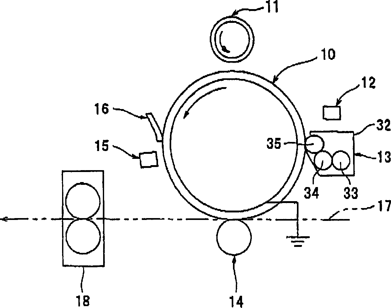
In cleaning devices, process cartridges and image forming devices, a cleaning structure with low linear pressure and high surface pressure can be obtained by specifying the material, shape and support structure of the cleaning blade. Press the front end corners of the elastic cleaning blade (38) supported by the so-called sheet holder, that is, the supporting member (37), on the roller-shaped and belt-shaped image carrier (10), and remove the residue remaining on the image carrier after image transfer. body toner. In such a cleaning device (16), the angle (θ) forming the front end corner line portion (36) of the cleaning blade is formed as an obtuse angle, and the front end corner line portion is formed at a surface pressure greater than or equal to 2.0 g / mm2. Press on the image carrier. The so-called surface pressure refers to the value obtained by dividing the total load applied to the cleaning blade by the contact area of the cleaning blade with respect to the member to be cleaned.
Description
technical field [0001] The present invention relates to an image forming apparatus such as a transfer machine, a printer, a facsimilemachine, or a composite machine of these. Among them, in particular, it relates to an electrophotographic image forming apparatus that forms a toner image on an image carrier, transfers the toner image directly or indirectly, and records the image on a recording medium such as paper or OHP film. It also relates to a cleaning device for removing toner remaining on an image carrier after image reproduction in such an image forming apparatus. And it is related with the process cartridge which at least integrally includes a cleaning device and an image carrier, and these are attached to and detachable from the main body of an image forming apparatus together. Background technique [0002] Conventionally, in an image forming apparatus of an electrophotographic type, the peripheral surface of a roll-shaped and belt-shaped image carrier is uniformly...
Claims
Application Information
Patent Timeline
Application Date:The date an application was filed.
Publication Date:The date a patent or application was officially published.
First Publication Date:The earliest publication date of a patent with the same application number.
Issue Date:Publication date of the patent grant document.
PCT Entry Date:The Entry date of PCT National Phase.
Estimated Expiry Date:The statutory expiry date of a patent right according to the Patent Law, and it is the longest term of protection that the patent right can achieve without the termination of the patent right due to other reasons(Term extension factor has been taken into account ).
Invalid Date:Actual expiry date is based on effective date or publication date of legal transaction data of invalid patent.

