Heat treated profile extruded hook

A technology of granular fillers and thermoplastic resins, applied in apparel, applications, fasteners, etc., can solve problems such as difficult productivity and narrow hook structure

Inactive Publication Date: 2006-05-10
3M INNOVATIVE PROPERTIES CO
View PDF25 Cites 9 Cited by
  • Summary
  • Abstract
  • Description
  • Claims
  • Application Information

AI Technical Summary

Problems solved by technology

However, the limitation of this manufacturing method is that the formed hook structure is extremely narrow in the extrusion or cutting direction of the rib.
Difficult to cut formed ribs at very close intervals at commercially acceptable production rates

Method used


Image

  • Heat treated profile extruded hook
  • Heat treated profile extruded hook
  • Heat treated profile extruded hook

Examples


Embodiment 1

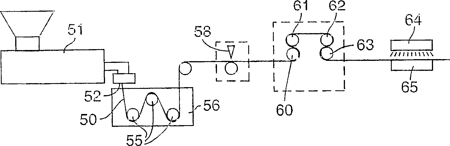
[0092] The web of Comparative Example C1 was subjected to the hook side on its side by conveying the web under a 36 cm wide ribbon flame burner Aerogen (Alton Hampshire, UK) at a speed of 90 m / min and at a distance of 8 mm from the burner. Non-contact heat treatment. The flame power is 74KJ / hour. The smooth base film side of the web was supported on chilled rolls at a temperature of about 18°C. Figure 6a and 6b An approximate outline of such a heat-treated hook is shown in . The performance of this hook material on nonwoven loop material 'A' was tested using a 135 degree peel test and the results are set forth in Table 1 below. The peel force of the heat-treated web was about 63% greater than that of Comparative Example C1 without heat treatment.

Embodiment 2

[0094] The web of Comparative Example C1 was subjected to non-contact heat treatment on its hooked side by conveying the web under a bank of 6-1000 watt, 1 micron wavelength infrared bulbs at a speed of 2.1 m / min. The distance between the hook and the bulb is about 2.5cm. The smooth base film side of the web was supported on chilled rolls at a temperature of approximately 66°C. Figure 7a and 7b An approximate outline of such a heat-treated hook is shown in . The performance of this hook material on nonwoven loop material 'A' was tested using a peel test and the results are given in Table 1 below. The 135° peel force of the heat-treated web was approximately 206% greater than that of Comparative Example C1 without heat treatment.

Embodiment 3

[0098] The web of Comparative Example C2 was subjected to non-contact heat treatment on its hooked side by conveying the web under a bank of 6-2000 watt, 1 micron wavelength infrared bulbs at a speed of 3.0 m / min. The distance between the hook and the light bulb is about 1.6cm. The smooth base film side of the web was supported on chilled rolls at a temperature of approximately 66°C. The performance of this hook material on nonwoven loop material 'A' was tested using a peel test and the results are given in Table 1 below. The 135° peel force of the heat-treated web was about 37% greater than that of Comparative Example C2 without heat treatment.


PUM


Abstract

A method for forming an integral polymeric protrusion or fastener comprising a thin and strong flexible backing and a plurality of thin, separate hook elements from The upper surface of the integral backing protrudes. The method generally includes extruding a thermoplastic resin through a die plate shaped to form a base layer and separate ridges, ribs or hook elements protruding from one surface of the base layer. When the mold forms the separate ridges or ribs, the cross-section of the hook element is formed by a die plate while the ridge is formed by cutting the ridge transversely at spaced locations along the length of the ridge to form the initial thickness of the hook element discontinuous cutting segment. Subsequently, longitudinal stretching of the backing layer (in the direction of the spine in the machine direction) separates these cut sections of the spine, which then form separate hook elements. The extruded hook element or the cut ribbed hook element is heat treated such that at least a portion of the head of the hook element shrinks in thickness by 5 to 90%, preferably 30-90%.

Description

technical field [0001] The present invention relates to molded hook fasteners for use with hook and loop fasteners. Background technique [0002] There are many known methods for forming hook materials for hook and loop fasteners. One of the first manufacturing methods for forming hooks involves weaving loops of monofilament into a fibrous or film-like or similar backing or the like, and then cutting the filamentary loops to form the hooks. The loops of these monofilaments are also heated to form headed structures, such as disclosed in US Pat. Nos. 4,290,174, 3,138,841 or 4,454,183. These braided hooks are generally durable and reusable, however, they are usually expensive and rough to the touch. [0003] For disposable clothing and the like, it is generally desirable to provide hooks that are inexpensive and less abrasive. For these and similar applications, a continuous extrusion process is often employed which simultaneously forms the backing and hook elements or hook ...

Claims


Application Information

Patent Timeline
Patent Type & Authority Applications(China)
IPC IPC(8): A44B18/00
Inventor 罗纳德·W·奥森威廉·C·昂鲁菲利普·米勒贾伊施里·塞思
Owner 3M INNOVATIVE PROPERTIES CO
Why Eureka
Try Eureka