A Manufacturing Technology of Dense Saber Coaming Hinge

A manufacturing technology, tooth plate technology, applied in the manufacturing field of dense saber-tooth coaming hinges, can solve the problems of poor load-bearing capacity, small stability, unable to meet the needs of packaging, etc., to achieve high strength, thick box plate, and firm connection Effect

Active Publication Date: 2019-03-12
WUXI TAYLOR PACKAGING ENG CO LTD
View PDF6 Cites 0 Cited by
  • Summary
  • Abstract
  • Description
  • Claims
  • Application Information

AI Technical Summary

Problems solved by technology

[0004] The purpose of the present invention is to provide a manufacturing technology of dense saber-tooth coaming hinges, which solves the problem that the existing art coaming hinges have low connection strength, poor load-bearing capacity, and small stability, and cannot meet the needs of packaging in many cases. question

Method used


Image

  • A Manufacturing Technology of Dense Saber Coaming Hinge

Examples


Embodiment 1

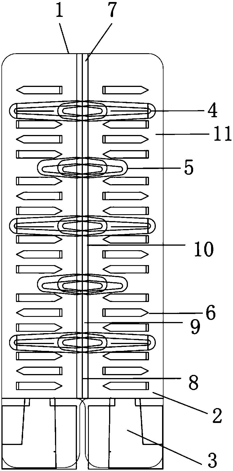
[0023] Such as figure 1 As shown, a manufacturing technology of dense saber-tooth coaming hinge, including hinge plate 1, saber-tooth plate 2, saber-tooth plate foot 3, hinge plate long transverse ridge 4, hinge plate short transverse ridge 5, sword Teeth 6, link plate 7, link bushing 8, bushing notch 9, hinge shaft 10, saber-tooth plate 11.

[0024] First, the saber-tooth plate 2 and the link plate 7 are set on the hinge plate 1, and then the saber-tooth plate foot 3, the long transverse ridge of the hinge plate 4, and the short hinge plate are set on the saber-tooth plate 2. Transverse ridges 5, saber teeth 6 and saber tooth plates 11.

[0025] Then, the link bushing 8 and the bushing notch 9 are arranged on the link plate 7 . Finally, the hinge plates 1 that match the two link bushings 8 and the bush gaps 9 are matched together, and the hinge shaft 10 is set in the link bushing 8 to complete a dense saber-tooth coaming Hinge implementation.

Embodiment 2

[0027] Such as figure 1 As shown, a kind of dense saber-tooth coaming hinge manufacturing technology also includes the following steps:

[0028] Step 1, material preparation: stamping and cutting the steel plate into steel sheets with the shape and size of the hinge plate,

[0029] Step 2, stamping the hinge slab: (1) Stamping the long transverse ridges of the hinge plate and the short transverse ridges of the hinge plate on the steel sheet at equidistant intervals from the inside to the outside, (2) further pressing the steel plate Stamping into two vertical faces, a narrow face and a wide face, and then cut off a section at one end of the narrow face to make a hinge slab,

[0030] Step 3. Stamping the saber-toothed plate: (1) stamping the protruding end of the wide surface of the hinge slab to form a streamlined outwardly curved saber-toothed plate foot and a said saber-toothed plate. The saber-tooth plate foot and the saber-tooth plate are parallel planes, (2) stamping th...


PUM


Abstract

The invention discloses a dense sword-tooth coaming hinge and a manufacturing technique thereof. The dense sword-tooth coaming hinge comprises hinge plates, sword tooth plates, sword tooth plate feet, hinge plate long transverse ridged protrusions, hinge plate short transverse ridged protrusions, sword teeth, connecting plates, connecting shaft sleeves, shaft sleeve notches, a hinge shaft and sword tooth plate pieces, and is characterized in that the dense riveting sword teeth integrated with the hinge plates are arranged by the adoption of a stamping method, the tooth height is 24 MM or above, the tooth width is 3.8 MM or above, and the tooth number is 16*2 or above. The manufacturing technique includes the first step of preparing materials, the second step of stamping hinge plate blanks, the third step of stamping the sword tooth plates, the fourth step of stamping the connecting plates, and the fifth step of matching the two hinge plates together and arranging the hinge shaft, wherein the second step of stamping the hinge plate blanks includes the substeps of (1) stamping the hinge plate long transverse ridged protrusions and the hinge plate short transverse ridged protrusions and (2) stamping the hinge plate blanks; and the third step of stamping the sword tooth plates includes the substeps of (1) stamping the sword tooth plate feet and the sword tooth plate pieces and (2) stamping the sword teeth. The dense sword-tooth coaming hinge is high in connection firmness and can meet packaging requirements. The defects in the prior art are overcome.

Description

technical field [0001] The invention relates to the technical field of hardware processing, in particular to a manufacturing technology of dense saber-tooth coaming hinges. Background technique [0002] The coaming hinge of the prior art is formed by opening 4 small holes symmetrically and riveting the plates with rivets. The process is complicated, the output is low, and the diameter of the rivets is small and the number is small, resulting in low connection strength, poor load-bearing capacity, and small stability, which cannot meet the needs of packaging in many cases. [0003] The dense saber-tooth coaming hinge of the present invention adopts the stamping method to set dense riveted saber teeth integrated with the dense saber-tooth coaming hinge, the tooth height is more than 24mm, the tooth width is more than 3.8mm, the number of teeth is more than 16×2, and the hinge plate The thickness is about 1-1.7mm. The present invention is combined with plywood or solid wood bo...

Claims


Application Information

Patent Timeline
Patent Type & Authority Patents(China)
IPC IPC(8): F16C11/04B21D53/40B23P21/00
CPCB21D53/40B23P21/00F16C11/04
Inventor 王天佑
Owner WUXI TAYLOR PACKAGING ENG CO LTD
Why Eureka
Try Eureka