Machine room-less elevator

A technology of machine room-less elevators and elevator shafts, which is applied to elevators, hoists, transportation and packaging in buildings to achieve the effect of improving space efficiency

Inactive Publication Date: 2006-05-17
TOSHIBA ELEVATOR KK
View PDF0 Cites 14 Cited by
  • Summary
  • Abstract
  • Description
  • Claims
  • Application Information

AI Technical Summary

Problems solved by technology

There is still room for improving the space efficiency of the machine room-less elevator system by changing the position of the control panel CP for controlling the operation of the drive device 4

Method used


Image

  • Machine room-less elevator
  • Machine room-less elevator
  • Machine room-less elevator

Examples


Embodiment Construction

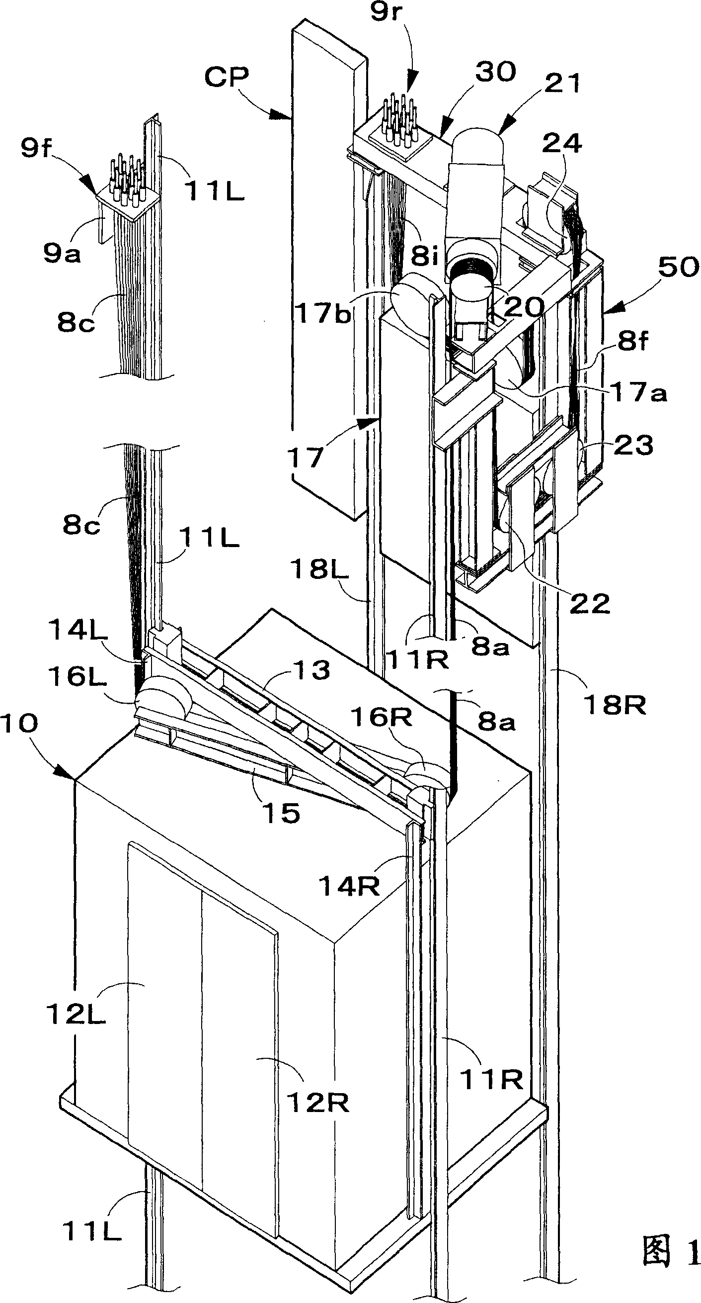
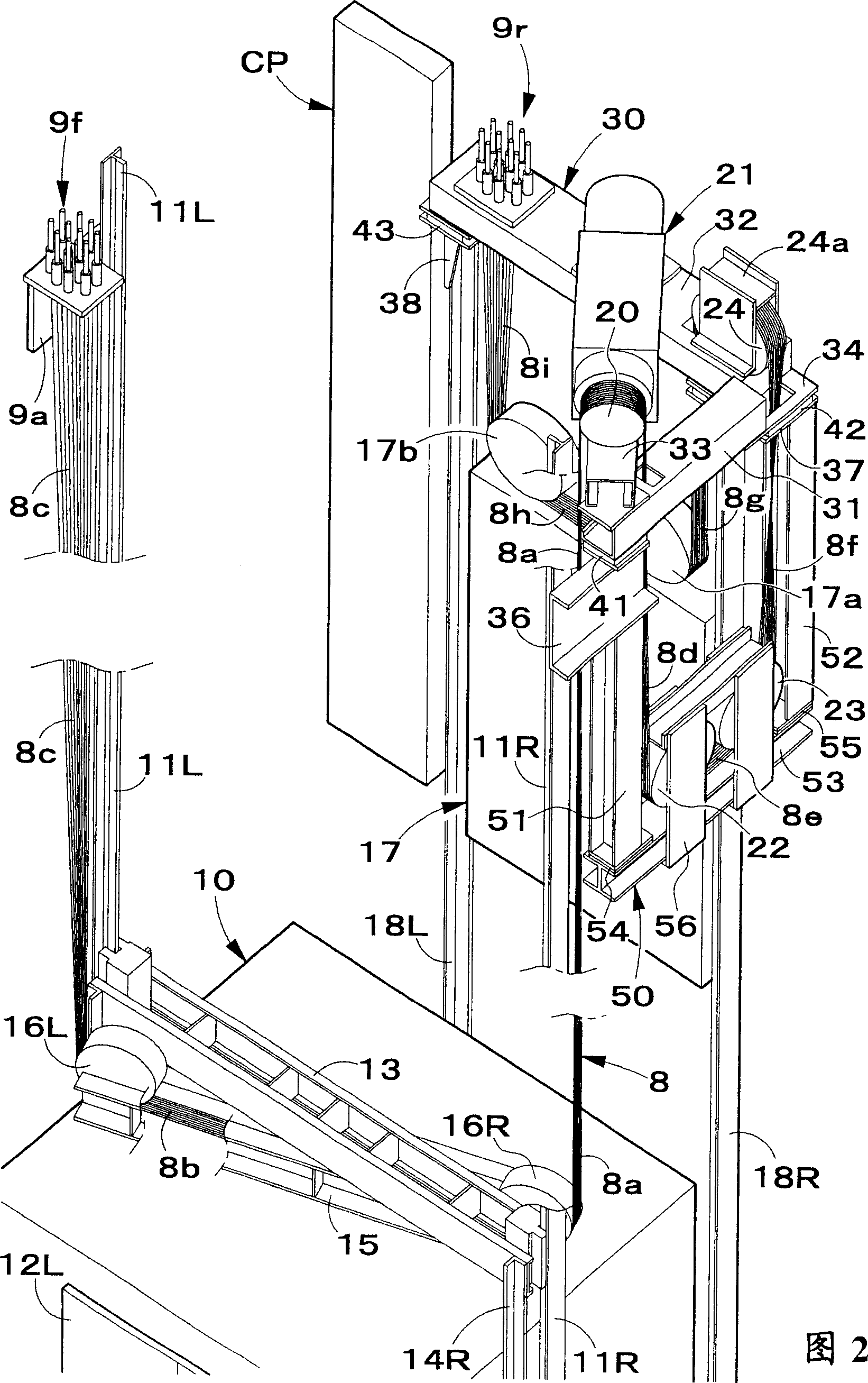
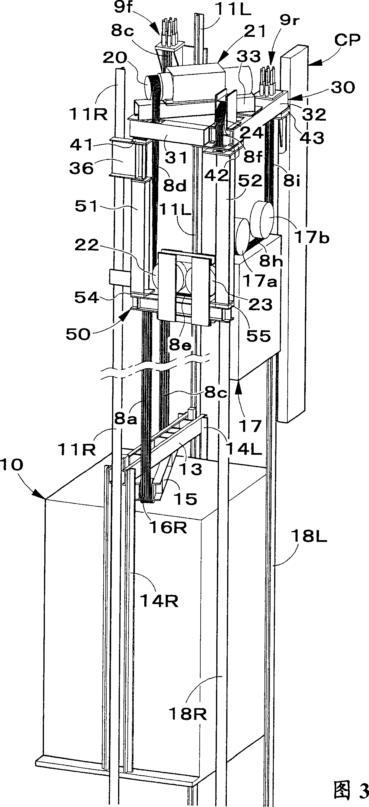
[0050] Next, a machine room-less elevator system according to a preferred embodiment of the present invention will be described with reference to FIGS. 1-5. In the following description, the direction in which the car door moves is called the horizontal direction, the direction in which passengers walk out of the car is called the forward direction, the direction in which passengers enter the car is called the backward direction, and the direction in which the elevator car moves is called the for the vertical direction. and Image 6 Corresponding parts of the hoisting member of the machine-room-less elevator system shown in FIG. 1 are indicated by the same reference numerals.

[0051] The machine room-less elevator system according to the preferred embodiment of the present invention shown in FIGS. 1-5 has a car 10 guided by a right car guide rail 11R and a left car guide rail 11L in an elevator shaft formed in a building. Move vertically in S. The right door 12R and the lef...


PUM


Abstract

When the car and the counterweight rise and fall, the vibration generated in the driving device and the upper and lower steering sheaves will not be transmitted from the guide rail to the wall of the elevator shaft. A vibration isolation device (41, 42, 43). In addition, vibration isolation devices (54, 55) are held between the vertical pieces (51, 52) and the horizontal pieces (53) of the support frame (50) supporting the lower diverting sheaves (22, 23). This cuts off the transmission of vibrations from the drive (21), the upper deflection sheave (24) and the lower deflection sheave (22, 23) to the side walls of the elevator shaft.

Description

technical field [0001] The invention relates to a machine room-less elevator system without a machine room above the elevator shaft. More specifically, the present invention relates to a technique for blocking transmission of vibrations generated by a drive unit and a diverting sheave when a car and a counterweight move vertically to the side walls of an elevator shaft. Background technique [0002] Various machine room-less elevator systems having no machine room above the elevator shaft have been proposed in order to efficiently utilize the space within the building and avoid problems related to direct sunlight and the like. Image 6 A machine room-less elevator system previously proposed by the applicant of the patent application for the present invention is shown. exist Image 6 In the shown machine-room-less elevator system, a counterweight 2 is supported behind a car 1 guided by left and right car guide rails, not shown, so as to move vertically in an elevator shaft. ...

Claims


Application Information

Patent Timeline
IPC IPC(8): B66B7/00B66B11/04B66B7/02B66B11/00
CPCB66B7/027B66B11/008B66B11/04
Inventor 和泉一裕川崎干浅见郁夫石井隆史浦田尚纪藤村俊东雅之仓光昌裕
Owner TOSHIBA ELEVATOR KK
Why Eureka
Try Eureka