

Rotary cultivator
A technology of rotary tiller and plough, applied in the field of rotary tiller, can solve the problems of hard and smooth bottom surface of rotary tiller, and the soil cannot be well mixed, etc.
- Summary
- Abstract
- Description
- Claims
- Application Information
AI Technical Summary
Problems solved by technology
Method used
Image

Examples
Embodiment Construction
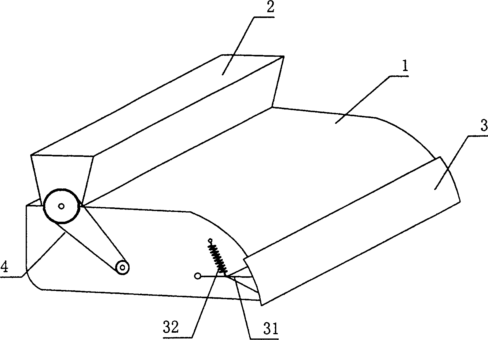
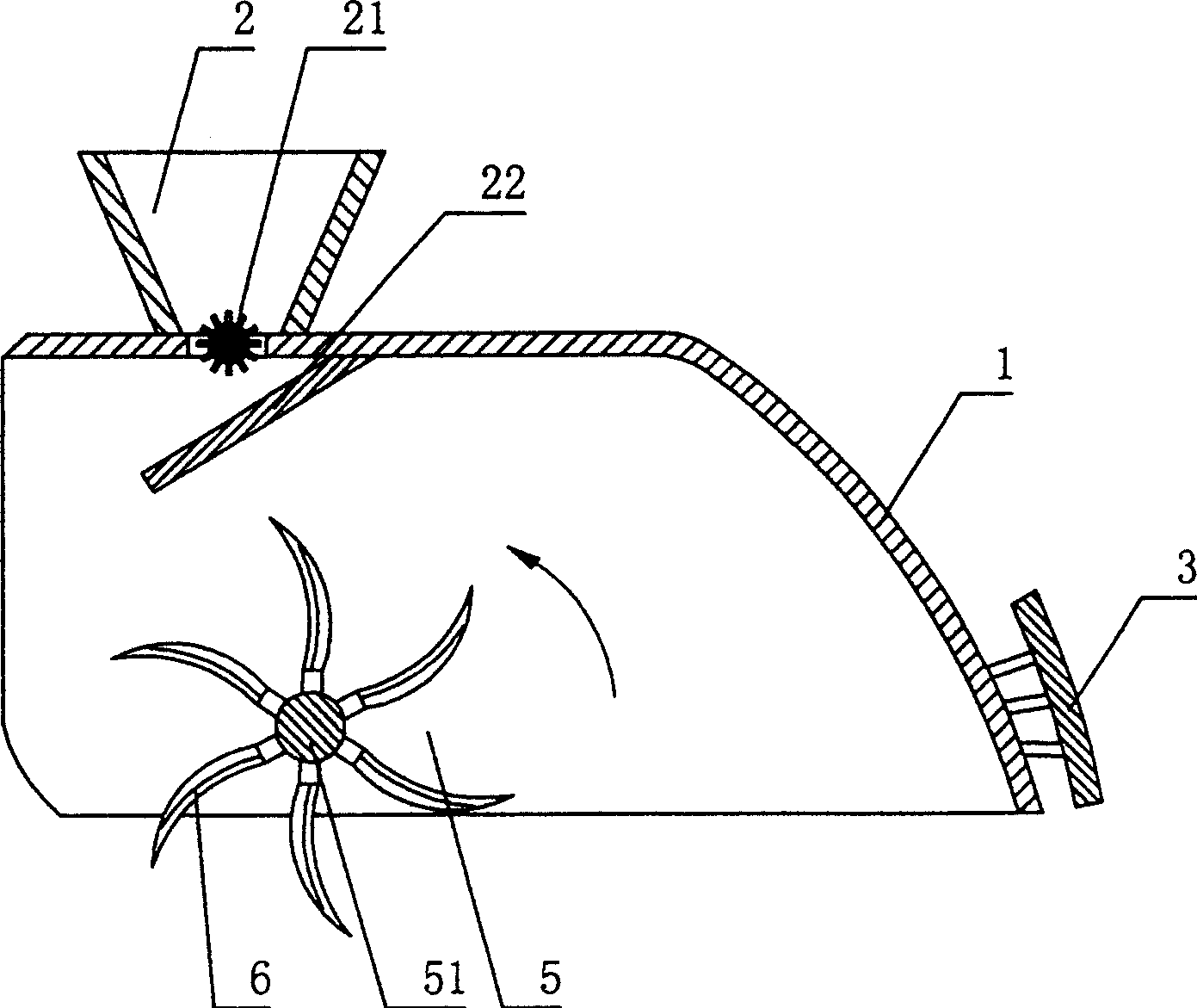
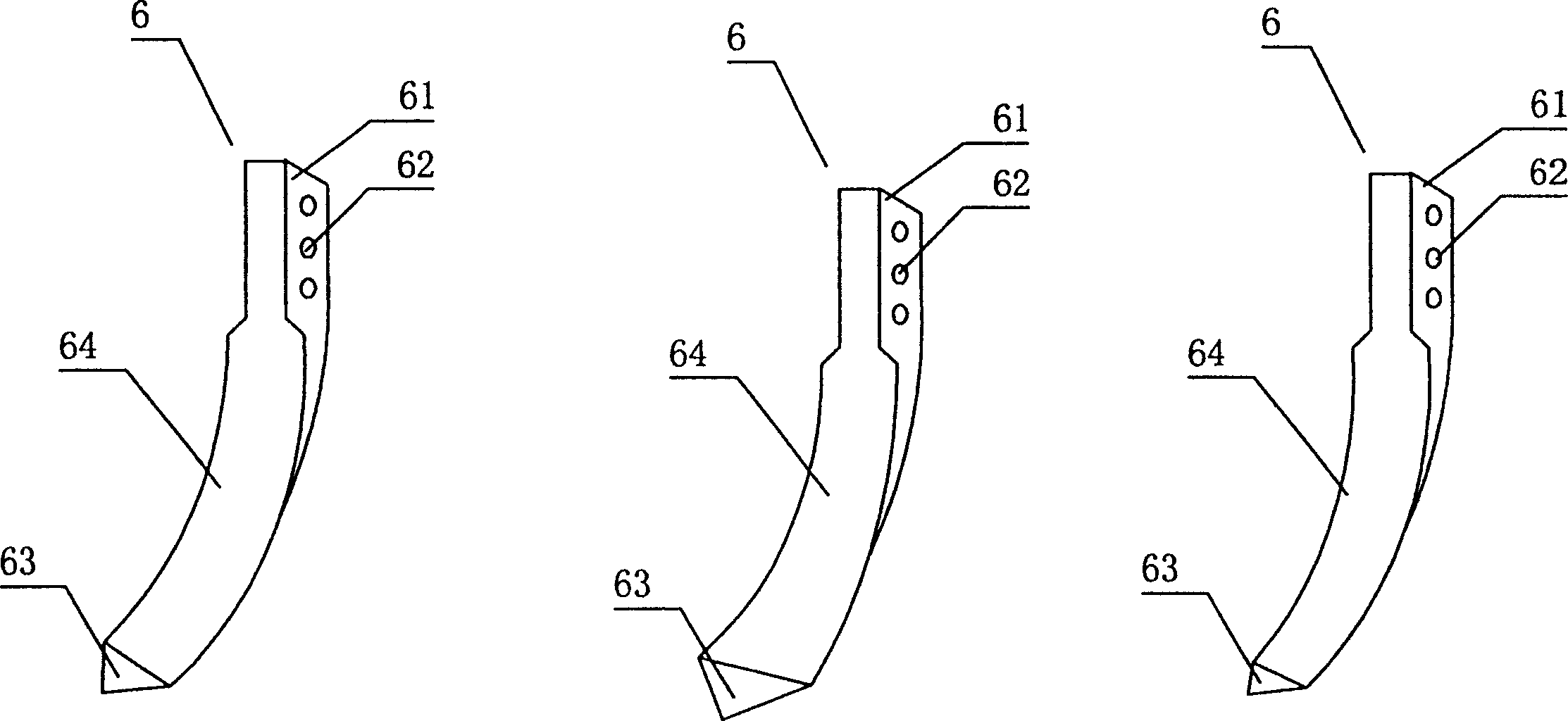
[0020] refer to figure 1 with figure 2 , a kind of rotary tiller of the present invention is: it is an agricultural implement that can work under the drive of traction machine, comprises the rotary tillage plow 5 that is located on the frame, can cover and buckle the rotary tillage plow 5 to play safety protection The fender 1, and the drag plate 3 for leveling the land after rotary tillage, the rotary plow 5 includes a plurality of rotary knives 6 that can turn up the soil and make the soil lift back and collide with the fender 1, and the rotary knives can be fixed 6 cutter shafts 51. The rotary plow 5 can work under the drive of the transmission mechanism on the fertilization of the rotary tiller. The fender 1 buckles the cover of the rotary plow 5 on its front and bottom, and the rear of the fender 1 is provided with a mop plate 3 for leveling the ground. Drag flat plate 3 is that activity is arranged on the rear of fender 1, as can adopt as figure 1 The connecting rod ...
PUM
 Abstract
Description
Claims
Application Information