
Backlight device, method of driving backlight and liquid crystal display apparatus

A backlight device, white light technology, used in optics, nonlinear optics, static indicators, etc.

Inactive Publication Date: 2006-05-24
SONY CORP
View PDF3 Cites 36 Cited by
  • Summary
  • Abstract
  • Description
  • Claims
  • Application Information

AI Technical Summary

Problems solved by technology

[0009] If the initial amount of current is not set properly, and therefore the time interval until convergence to a determined chromaticity is long, there will be a phenomenon where the screen initially appears pink and then the color gradually approaches white

Method used


Image

  • Backlight device, method of driving backlight and liquid crystal display apparatus
  • Backlight device, method of driving backlight and liquid crystal display apparatus
  • Backlight device, method of driving backlight and liquid crystal display apparatus

Examples


Embodiment Construction

[0033] Embodiments of the present invention will be described in detail below with reference to the accompanying drawings.

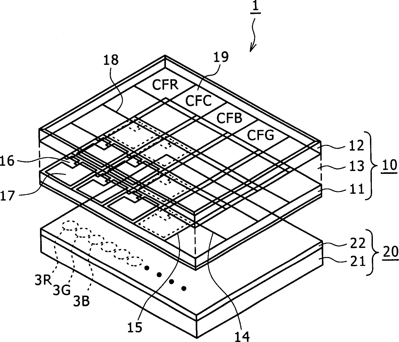
[0034] The present invention is applied to a color liquid crystal display device having, for example, a figure 1 A backlight liquid crystal display unit 1 of the structure shown.

[0035] (Structure of liquid crystal display unit)

[0036] The liquid crystal display unit 1 includes: a transparent color liquid crystal display panel 10 ; and a backlight device 20 disposed on the back of the color liquid crystal display panel 10 .

[0037] (plate)

[0038] The transparent color liquid crystal display panel 10 includes: a TFT substrate 11 facing each other, a counter electrode (counter electrode) substrate 12; twisted nematic (TN) liquid crystals. Formed on the TFT substrate 11 are: signal lines 14 and scanning lines 15 arranged in matrix; thin film transistors 16 as switching elements arranged at intersections between the signal lines 14 and scanning li...


PUM


Abstract

The present invention can prevent the prolongation of the time interval from energizing the device to converging the chromaticity of emitted white light to a definite chromaticity regardless of the temperature at which the device is energized. A color liquid crystal display device comprises: a liquid crystal display unit; a backlight, which adopts red, green, and blue LEDs as its light source; a driving unit, which is used to drive the LEDs of each color; a temperature sensor, which is used to sense the temperature of the LEDs and a chromaticity sensor for sensing the chromaticity of the white light emitted from the LED. The driving unit supplies current to the LEDs to drive them, and performs feedback control of the current amount for each color of the LED based on the value sensed by the chromaticity sensor so that white light has a certain chromaticity. In addition, when the backlight is powered on, the drive unit retrieves the initial current value of each color LED from the nonvolatile memory, and corrects the initial current value according to the value sensed by the temperature sensor to activate each color LED using the corrected value. LED.

Description

[0001] Cross References to Related Applications [0002] This application contains subject matter of Japanese Patent Application No. JP 2004-336572 filed in Japan Patent Office on Nov. 19, 2004 and Japanese Patent Application No. JP 2005-232385 filed in Japan Patent Office on Aug. 10, 2005, which The entire contents are hereby incorporated by reference. technical field [0003] The present invention relates to a backlight device provided at the back of a non-emissive transmission display, a method of driving the backlight, and a liquid crystal display device. Background technique [0004] As a backlight of a liquid crystal panel, a cold cathode fluorescent lamp (CCFL) type backlight using a fluorescent tube has become mainstream. However, due to environmental concerns, there is an increasing demand for mercury-free products. In recent years, these demands have raised expectations to use light emitting diodes (LEDs) instead of CCFLs as light sources. Specifically, a method...

Claims


Application Information

Patent Timeline
Patent Type & Authority Applications(China)
IPC IPC(8): G02F1/1335G02F1/133
Inventor 市川弘明菊地贤一畑尻公夫
Owner SONY CORP
Learn More