Particle dispersing method and its device

A particle and dispersion technology, applied in mixing methods, chemical instruments and methods, mixers, etc., can solve the problems of high production cost, difficult to control dispersion effect, complicated equipment, etc., and achieve the goal of reducing production cost, simple equipment and flexible control. Effect

Inactive Publication Date: 2006-06-07
HONG FU JIN PRECISION IND (SHENZHEN) CO LTD +1
View PDF3 Cites 4 Cited by
  • Summary
  • Abstract
  • Description
  • Claims
  • Application Information

AI Technical Summary

Problems solved by technology

[0009] In order to overcome the shortcomings of complex equipment used in the particle dispersion method in the prior art, high production costs, and difficulty in controlling the dispersion effect, etc.

Method used


Image

  • Particle dispersing method and its device
  • Particle dispersing method and its device
  • Particle dispersing method and its device

Examples


Embodiment Construction

[0024] The present invention will be described in further detail below in conjunction with the accompanying drawings.

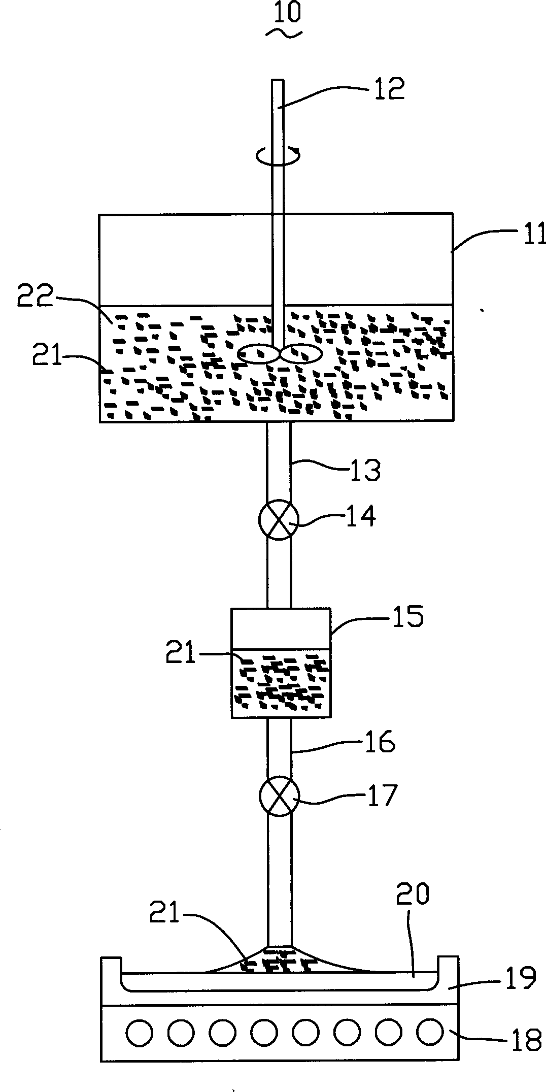
[0025] see figure 2 , the particle dispersing equipment 10 provided by the present invention comprises a container 11, which can be a rectangular, cylindrical or funnel-shaped container with a stirring device 12 attached; an upper conduit 13 connected to the bottom of the container 11 is provided with a The first switch element 14 is used to control the export of the solution in the container 11; an ultrasonic oscillator 15, which communicates with the container 11 through the upper conduit 13, and the first switch element 14 can control the flow entering the ultrasonic oscillator 15; The downcomer 16 used for the derivation of the solution in the ultrasonic oscillator 15 is provided with a second switch element 17; and a heating device 18 is provided with a heating tank 19 for receiving the uniformly dispersed particle solution, When the above equipment is...


PUM


Abstract

The particle dispersing method includes the following steps: mixing the particle to be dispersed with surfactant via stirring to form suspension; ultrasonically vibrating the mixed suspension for set time; mixing the vibrated solution with base material; and heating the base material to evaporate the surfactant. The corresponding particle dispersing apparatus is also provided. The present invention has excellent dispersion effect, and the method may be used in adding nanometer particle into heat interface material.

Description

【Technical field】 [0001] The invention relates to a particle dispersion method, in particular to a particle dispersion method and equipment using ultrasonic vibration. 【Background technique】 [0002] Due to the effect of van der Waals force, the smaller the particles, the more obvious the agglomeration phenomenon, such as the agglomeration of nanoparticles is extremely easy, which will lead to the decline of its nanometer performance and affect the application and development of nanotechnology. [0003] Therefore, the nanoparticles must be fully dispersed, and the greater the degree of dispersion, the better the effect and the more fully the nano-related properties can be used. Usually adding nanoparticles (such as nano-metals or carbon nanotubes) to the thermal interface material can improve the thermal conductivity of the thermal interface material and increase the thermal conductivity. Among them, nanoparticles need to be uniformly dispersed in the thermal interface mate...

Claims


Application Information

Patent Timeline
Patent Type & Authority Applications(China)
IPC IPC(8): B01F3/12B01F11/02
CPCB82Y30/00B01F23/511B01F23/551B01F23/53B01F27/70B01F31/86B01F33/8212
Inventor 颜士杰
Owner HONG FU JIN PRECISION IND (SHENZHEN) CO LTD
Why Eureka
Try Eureka