Hollow pipe of concrete

A hollow tube and tube body technology, which is applied in the direction of formwork/formwork/work frame, building components, and on-site preparation of building components, which can solve the problems of inconvenient transportation and construction, heavy weight, etc.

Inactive Publication Date: 2006-06-07
湖南邱则有专利战略策划有限公司
View PDF3 Cites 1 Cited by
  • Summary
  • Abstract
  • Description
  • Claims
  • Application Information

AI Technical Summary

Problems solved by technology

However, when the number of stiffeners provided on this hollow tube member is ...

Method used


Image

  • Hollow pipe of concrete
  • Hollow pipe of concrete
  • Hollow pipe of concrete

Examples


Embodiment Construction

[0053] The present invention will be further described below in conjunction with the accompanying drawings and embodiments.

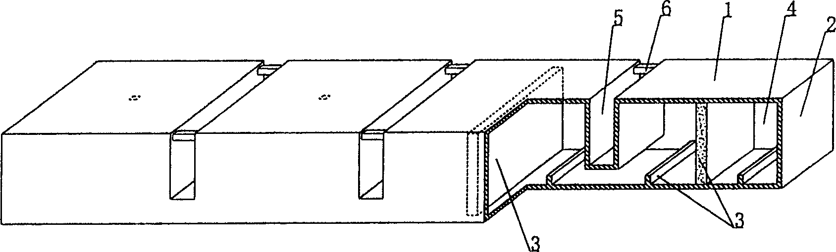
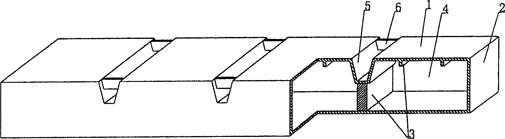
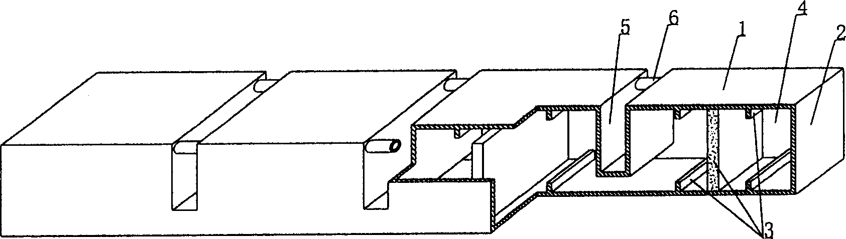
[0054] As shown in the accompanying drawings, the present invention includes a pipe body 1, a pipe end cap 2, and a stiffener 3. The stiffener 3 is a stiffening rib, and the two pipe end caps 2 seal off both ends of the pipe body 1 to form a closed cavity 4. The stiffener 3 is arranged in the cavity 4, and is characterized in that at least one groove 5 is arranged on the pipe body 1, at least one brace member 6 is arranged in the groove 5, and at least two grooves 5 are arranged in parallel. figure 1 It is a structural schematic diagram of Embodiment 1 of the present invention. In the accompanying drawings, 1 is the pipe body, 2 is the pipe end head, 3 is the stiffener, 4 is the closed cavity, 5 is the groove, and 6 is the supporting part. In the following drawings, the numbers are the same, and the description same. Such as figure 1 As shown, the tw...


PUM


Abstract

The hollow pipe for concrete includes pipe body, end plates and reinforcing parts. The two end plates clock the two ends of the pipe body to form closed cavity; and the reinforcing parts are at least one kind of reinforcing rib, reinforcing rod and reinforcing cable set inside the cavity. The hollow pipe for concrete features its notches including at least two parallel ones and with at least one staying part. The present invention is suitable for use in in-situ cast or pre-stressed reinforced concrete hollow floor slab, roof, base slab, wall and bridge.

Description

[0001] This application is a divisional application of an invention patent application with an application date of June 19, 2003, an application number of 03143177.1, and a title of “A Hollow Tube for Concrete”. (1) Technical field [0002] The invention relates to a hollow pipe for concrete. (2) Background technology [0003] At present, in the existing technology, the hole-forming components of the cast-in-place concrete hollow floor are permanent mandrels, such as paper tubes, plastic tubes, metal bellows, mandrel lightweight materials, etc. These tubular mandrels or components are mainly considered to evacuate concrete , to reduce the weight of the floor. For example, the patent No. 99249755.8 applied by the applicant is a utility model patent for "fiber-reinforced thin-walled tube for filling cast-in-place reinforced concrete". It consists of a hard thin-walled tube and plugs at both ends. Both ends of the tube are closed to form a closed cavity, and the cross section ...

Claims


Application Information

Patent Timeline
IPC IPC(8): E04G15/06E04B5/17E04B5/36
Inventor 邱则有
Owner 湖南邱则有专利战略策划有限公司
Why Eureka
Try Eureka