
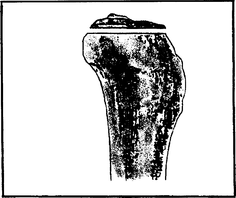
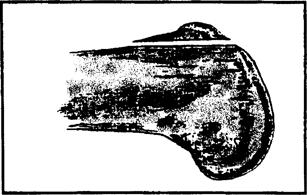
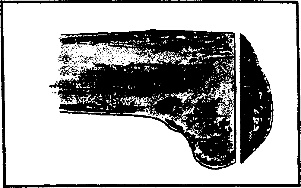
Femur formation and cutting center

A technology for femoral condyle and bone cutting, which is applied in the field of cutters for forming and processing femoral condyle at one time, can solve the problems of long operation time and unexpected situations, and achieves the effect of shortening operation time, reducing work intensity and reducing blood loss.

Inactive Publication Date: 2006-06-14
BEIJING MONTAGNE MEDICAL DEVICE
View PDF0 Cites 6 Cited by
  • Summary
  • Abstract
  • Description
  • Claims
  • Application Information

AI Technical Summary

Problems solved by technology

This often causes great pain to the patient, and may even lead to unexpected situations due to the long operation time

Method used


Image

  • Femur formation and cutting center
  • Femur formation and cutting center
  • Femur formation and cutting center

Examples


Embodiment Construction

[0023] Refer to the attached Figure 7 ~9 describes in detail a preferred embodiment of a femoral condyle shaping cutter 10 provided by the present invention. exist Figure 7 In the illustrated embodiment, the femoral condyle shaping cutter 10 provided by the present invention includes a main drive shaft 15 arranged in the transmission gearbox 4 . The main drive gear 14 installed on the main drive shaft 15 . The first driven gear 12 meshing with the main drive gear 14 is installed on the first driven shaft 13 . The first output shaft 13 is mounted in the transmission gearbox 4 . The main drive gear 14 meshes with an intermediate gear 16 , and the intermediate gear 16 is mounted on an intermediate shaft 17 . The intermediate shaft 17 is mounted in the transmission gearbox 4 . The intermediate gear 16 meshes with a second driven gear 18 mounted on a second driven shaft 19 supported in the transmission gearbox 4 .

[0024] from Figure 7 It can be seen from the figure that...


PUM


Abstract

A cutting center for shaping the femur condyle is composed of a speed variator, a main drive shaft in said speed variator, a main drive gear installed to said main drive shaft, at least one driven gear matched with said main drive gear and installed to the first driven shaft in said speed variator, and a cutter installed to the extended end of the first driven shaft.

Description

technical field [0001] The invention relates to a femoral condyle forming cutting center, in particular to a cutter for one-time forming processing of the femoral condyle. During use, the cutter for shaping and processing the femoral condyle provided by the present invention is installed on the knee joint by means of a fixing device, and multiple surfaces required for shaping are processed on the human femoral condyle at one time by sawing, milling, filing, and grinding. Background technique [0002] In some special cases, it is necessary to install a prosthesis at the knee joint of the human body. At this time, the femoral condyle must be reshaped and cut, so that the end of the femoral condyle has a specific shape, so that it can be fitted with the prosthesis that is suitable for it. [0003] Currently, during a total knee arthroplasty procedure to reduce an injured knee, orthopedic surgeons often spend a long time ensuring that the articulation of the knee is balanced. A...

Claims


Application Information

Patent Timeline
Patent Type & Authority Applications(China)
IPC IPC(8): A61B17/56A61B17/32A61F2/82
CPCA61B17/1624A61B17/1675
Inventor 周袭明
Owner BEIJING MONTAGNE MEDICAL DEVICE
Learn More