Electrical valve

An electric valve and valve body technology, applied in valve details, valve devices, engine components, etc., can solve the problems of manual switching, inconvenience in production and maintenance, and safety, and achieve the benefits of production and maintenance, standardization, and realization. generalized effect

Inactive Publication Date: 2006-06-14
INST OF AUTOMATION CHINESE ACAD OF SCI
View PDF0 Cites 8 Cited by
  • Summary
  • Abstract
  • Description
  • Claims
  • Application Information

AI Technical Summary

Problems solved by technology

Among them, the valve body of existing manual valves (such as ball valves, butterfly valves, gate valves, etc.) is provided with a movable part for opening and closing the valve. The movable part rotates the valve stem, which extends from the top of the valve body to the outside of the valve body. There is also a handle, and the valve can be opened and closed by turning the valve stem through the handle. The defect of this type of valve is that it must be switched manually, which is not only troublesome to operate, but also cannot be controlled automatically or remotely. It is a solenoid valve, and there is an electromagnet in the valve body. The electromagnet is mainly composed of a coil wound on a silicon steel sheet. After being energized, it relies on the magnetic force of the electromagnet to attract the same magnetic moving parts to realize the opening or closing of the valve. , because the defect of this type of valve is that the electric part is set in the valve body, it is easy to generate sparks or leakage, and there are safety hazards when used in gas pipelines and other occasions. In addition, due to the difference in internal structure between it and manual valves, the two Or the lack of interchangeability between parts also brings inconvenience to production and maintenance

Method used


Image

  • Electrical valve

Examples


Embodiment Construction

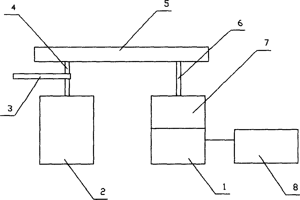
[0007] Referring to the accompanying drawings, the present invention relates to an electric valve, which includes a valve body 2 and a motor 1. The movable part in the valve body is provided with a valve stem 4 for controlling the opening and closing of the valve, and the valve stem extends from the top of the valve body to the outside of the valve body. , and is driven and connected to the motor through a transmission mechanism outside the valve body, and the motor is provided with a control device 8 for controlling its operation.

[0008] The present invention can be provided with a limiting device that limits the rotation range of the valve stem, so as to avoid damage to the internal structure of the valve body caused by excessive rotation of the valve stem.

[0009] Described position-limiting device can adopt any prior art, can comprise the position-limiting structure that is arranged on the rotating part (so-called position-limiting structure refers to a part or all on th...


PUM


Abstract

There is disclosed an electrically operated valve using a motor disposed outside a hand valve body. The motor has a control means controlling its work. Using a driving mechanism connects and drives the valve stem for opening and closing the valve. A spacing means in the valve and a overtravel-limit switch is used for limiting rotation range of the valve stem. When the valve uses a ball valve, the said motor can use DC motor with a speed reducer is connected with the valve stem via a gear pair, a friction wheel pair or a belt driving device. A driven gear or a driven friction wheel on the valve stem uses a fan wheel.

Description

technical field [0001] The invention relates to an electric valve. technical background [0002] Existing valves mainly include manual and electric two types. Among them, the valve body of existing manual valves (such as ball valves, butterfly valves, gate valves, etc.) is provided with a movable part for opening and closing the valve. The movable part rotates the valve stem, which extends from the top of the valve body to the outside of the valve body. There is also a handle, and the valve can be opened and closed by turning the valve stem through the handle. The defect of this type of valve is that it must be switched manually, which is not only troublesome to operate, but also cannot be controlled automatically or remotely. It is a solenoid valve, and there is an electromagnet in the valve body. The electromagnet is mainly composed of a coil wound on a silicon steel sheet. After being energized, it relies on the magnetic force of the electromagnet to attract the same mag...

Claims


Application Information

Patent Timeline
Patent Type & Authority Applications(China)
IPC IPC(8): F16K31/04
Inventor 郝宏朱凤华王知学
Owner INST OF AUTOMATION CHINESE ACAD OF SCI
Why Eureka
Try Eureka