Changable type carbon brush case for disc electric motor

A disc motor and carbon brush box technology, applied in the direction of rotating current collectors, circuits, current collectors, etc., can solve the problems of inability to take out or put in, inconvenient inspection or replacement of carbon brushes, etc., to achieve easy take out or put in Effect

Inactive Publication Date: 2006-06-14
TSINGHUA UNIV +1
0 Cites 2 Cited by

AI-Extracted Technical Summary

Problems solved by technology

The carbon brush holder is a fan-shaped insulating plate, which is fixed on the motor casing when the motor is assembled, a...

Method used

The end of a pivoted arm of brace spring 2 is supported on carbon brush bottom, and the end of another pivoted arm is supported on the carbon brush box box body, thereby carbon brush is pressed on commutator 5. Brace spring 2 can be made by steel wire. The ends of the two pivoting arms of the support spring 2 are provi...

Abstract

This invention discloses a changeable carbon brush box of a disk motor including a dismountable box mounted on the narrow shell of the disk motor, two copper jackets set at the front of the box in a certain angle, two carbon brushes in the copper jackets and a bracing spring set at the back of the box, in which, small rings are set at the ends of the two rotation arms of the spring and jacket the leads at the tails of the brushes to restrict the bracing spring, the end of one rotation arm of which supports the bottom of the brush, the end of the other supports the box and the carbon brush box shell can be covered by the cover of the box to become a flat integer mounted in the motor shell fixedly.

Application Domain

Technology Topic

Image

  • Changable type carbon brush case for disc electric motor
  • Changable type carbon brush case for disc electric motor
  • Changable type carbon brush case for disc electric motor

Examples

  • Experimental program(1)

Example Embodiment

[0019] The present invention will be further described below with reference to the drawings and embodiments.
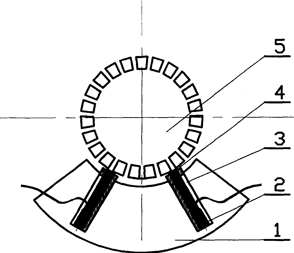
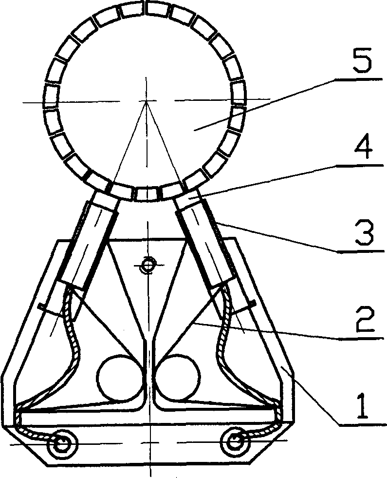
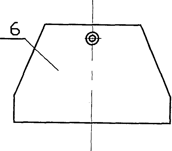
[0020] In a typical embodiment of the present invention, such as figure 2 As shown, the disc motor replaceable carbon brush box includes a carbon brush box body 1, two copper sleeves 3 placed in the carbon brush box body at a set angle (such as 45° or 60°), respectively Two carbon brushes 4 movably installed in the two copper sleeves, and a brace spring 2 arranged at the lower part of the carbon brush box box body. The carbon brush box box body is flat in this embodiment, and the cross-sectional shape of the carbon brush box box body is trapezoidal in this embodiment. The carbon brush box body is detachably installed in the narrow shell of the disc motor (see Figure 5 ), in this embodiment, screws are used to tighten the narrow shell of the disc motor.
[0021] The end of one rotating arm of the support spring 2 is supported on the bottom of the carbon brush, and the end of the other rotating arm is supported on the body of the carbon brush box, thereby pressing the carbon brush on the commutator 5. The spring 2 can be made of steel wire. The ends of the two arms of the spring 2 are equipped with small rings (see Figure 4 ), the small damage is sleeved on the lead at the tail of the carbon brush 4, and the carbon brush lead is used to connect and constrain the brace spring, so that the brace spring can reliably bear the carbon brush and ensure that the carbon brush is freely compressed and stretched. This structure achieves the purpose of reliable connection and restraint, and is a new connection method that has never been seen at home and abroad.
[0022] Such as image 3 As shown, the replaceable carbon brush box further includes a carbon brush box cover 6 for covering the support spring and the copper sleeve, and the carbon brush box cover and the carbon brush box body are detachably fastened together, Form a flat and thin whole. When the cover of the carbon brush box is closed, the carbon brush box becomes a flat and thin whole, and the whole can be easily taken out or put in the motor housing without disassembling the motor, which is convenient for installation and replacement of carbon brushes.
[0023] The replaceable carbon brush box of the disc motor of the present invention has been sampled and has been tried for a long time in the disc motor, which fully realizes the predetermined idea, is reliable in use, and convenient in disassembly and assembly.
[0024] The present invention is not limited to the foregoing embodiments. For those skilled in the art, the specific shape of the carbon brush box can be changed without departing from the spirit of the present invention and the protection scope of the claims.

PUM

no PUM

Description & Claims & Application Information

We can also present the details of the Description, Claims and Application information to help users get a comprehensive understanding of the technical details of the patent, such as background art, summary of invention, brief description of drawings, description of embodiments, and other original content. On the other hand, users can also determine the specific scope of protection of the technology through the list of claims; as well as understand the changes in the life cycle of the technology with the presentation of the patent timeline. Login to view more.

Similar technology patents

Fluid channel, motor with same and solid-liquid separation system

ActiveCN107159319ASmooth passageEasy to put in and take outFluid transfer labwareFluid controllersMotor shaftStator
Owner:唐凌霄

Teaching material storage device

InactiveCN113023062AConvenient overall organizationEasy to put in and take outExternal framesContainers to prevent mechanical damageStructural engineeringMaterial storage
Owner:WENZHOU POLYTECHNIC

Carton

InactiveCN102730263ANot easy to shakeEasy to put in and take outRigid containersFistEngineering
Owner:PEGATRON

Classification and recommendation of technical efficacy words

  • Easy to put in and take out

Distillatory kettle for plant sesame oil

ActiveCN104606909ASimple structureEasy to put in and take outDistillation in boilers/stillsEssential-oils/perfumesWater tanksHeat energy
Owner:GUANGXI BONENG BIOMASS ENERGY TECH CO LTD

Fluorescence detection instrument and system based on micro-fluidic chip

InactiveCN105388131AGood light protectionEasy to put in and take outFluorescence/phosphorescenceMicro fluidicMicrofluidic chip
Owner:THE NAT CENT FOR NANOSCI & TECH NCNST OF CHINA

Rotary tower type non-stop unwinding equipment

ActiveCN111532846AImprove efficiencyEasy to put in and take outWebs handlingWall plateIndustrial engineering
Owner:青州蒙特机械有限公司
Why Eureka
Try Eureka