Clutches

A clutch and clutch plate technology, applied in the field of clutches, can solve the problems of expensive progressive hydraulic control valves and imperfect systems

Inactive Publication Date: 2006-06-14
RICARDO UK LTD
View PDF0 Cites 8 Cited by
  • Summary
  • Abstract
  • Description
  • Claims
  • Application Information

AI Technical Summary

Problems solved by technology

However, progressive hydraulic pressure valves are extremely expensive
In attempting to obtain a predetermined rate-of-growth profile of the torque transmitted by the clutch, complex feedback systems are often used, and these systems are not perfect, which in practice makes the shift unacceptably jerky

Method used


Image

  • Clutches
  • Clutches
  • Clutches

Examples


Embodiment Construction

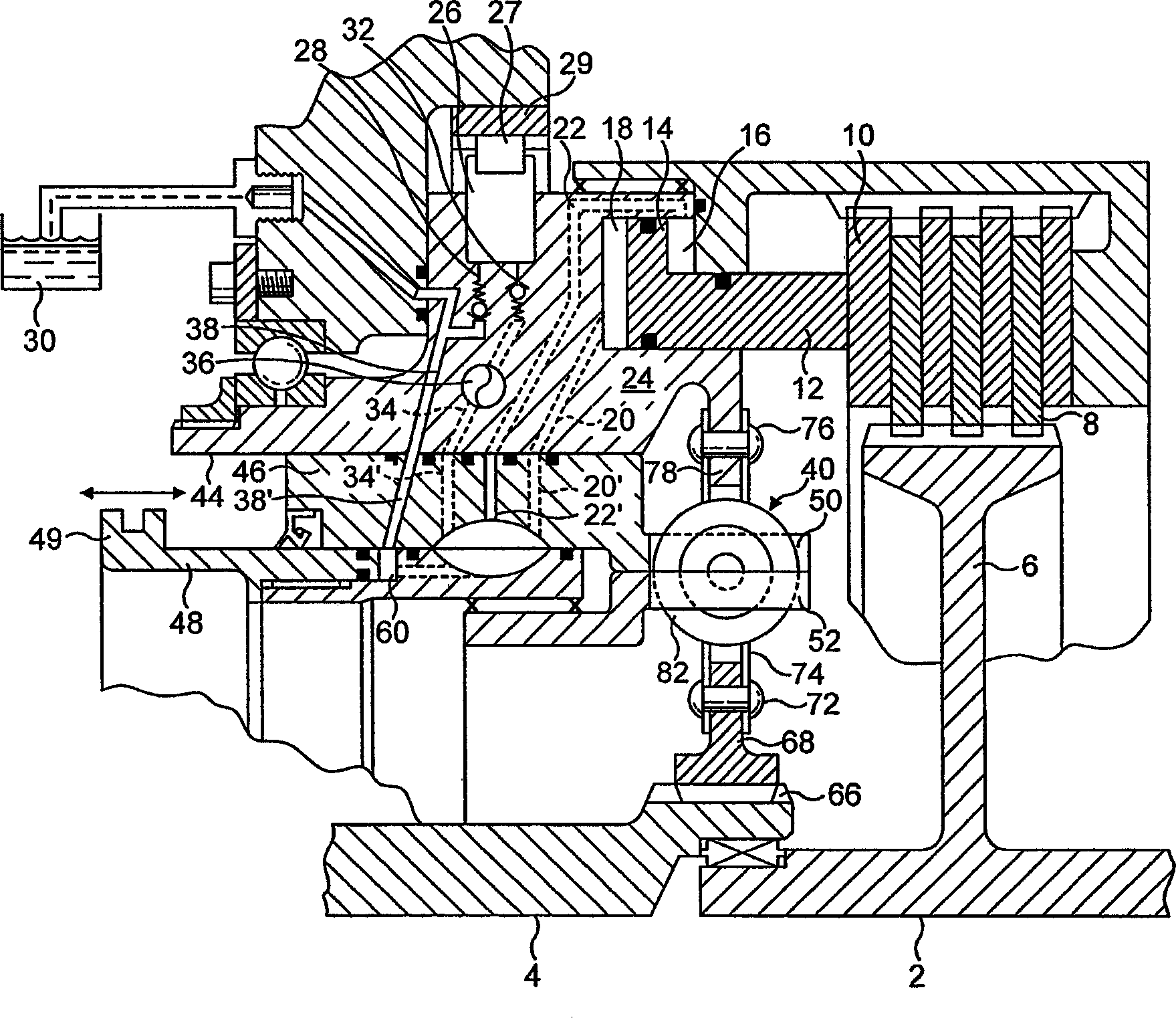
[0021] first reference figure 1 , the clutch includes an input shaft 2 and a coaxial output shaft 4 . A first set of annular clutch plates 8 meshes with a splined hub 6 carried by the input shaft 2, said first set of annular clutch plates cooperating with a second set of annular clutch plates 10 which are connected in Rotate together with the clutch body 24. Cooperating with the outermost clutch plate 10 is a clutch piston 12 , a part 14 of which is housed in a clutch cylinder whose interior is divided by the piston part 14 into two chambers 16 and 18 . Cavities 16 and 18 communicate with respective hydraulic fluid supply passages 20 and 22 extending within clutch body 24 . The clutch body 24 also accommodates a high-pressure hydraulic fluid pump 26, its inlet 28 communicates with an unpressurized hydraulic fluid tank or hydraulic fluid tank 30 via a check valve, and its outlet 32 ​​communicates with another hydraulic fluid supply line 34 , the hydraulic fluid supply line 3...


PUM


Abstract

A clutch including two rotary shafts, one of which is connected to one or more first clutch plates which cooperate with a second set of clutch plates, the clutch plates acted on by an actuating piston positioned within a two chamber hydraulic cylinder. A torque control valve comprising a cylindrical inner valve member rotatably and linearly movably received in a cylindrical opening in an outer valve member. Each valve member having elongate recesses positioned such that longitudinal movement of the inner valve member within the outer valve member will vary the degree of communication between the first and second elongate recesses connected to two hydraulic fluid sources of differing pressures. The second clutch plates are connected to one side of a spring of predetermined spring rate, which is also connected to one of the valve members, and the other side of the spring is connected to the other of the valve members and to the other rotary shaft.

Description

technical field [0001] This invention relates to clutches, in particular clutches for automobiles, and to clutches which can be controlled so that the torque they transmit is at a predetermined level or varies in a predetermined manner. The invention relates in particular to such a clutch for use in connection with a so-called manual automatic gearbox. Background technique [0002] Clutches intended for use with manual automotive transmissions are torque controlling in nature, but this torque control is done by the user. Thus, when the user releases the clutch to reconnect the engine output shaft to the gearbox after shifting, he releases the clutch gradually so that the torque transmitted to the gearbox increases progressively up to the maximum torque. The shifting is thus smooth, however if the clutch is released suddenly the shifting will be accompanied by an unacceptable jerk of the vehicle. [0003] However, manual automotive transmissions are gradually falling out of...

Claims


Application Information

Patent Timeline
Patent Type & Authority Applications(China)
IPC IPC(8): F16D48/04F16D25/0638F16D25/12F16D48/02
CPCF16D25/0638F16D48/02F16D48/04F16D2048/0215F16D2048/0221F16D2048/0284
Inventor 肖恩·埃旺·梅彭罗伯特·约翰·巴恩斯
Owner RICARDO UK LTD
Why Eureka
Try Eureka