Processing control method for gear lapping machine

A control method and technology for a gear grinding machine, applied in the field of gear grinding machines, can solve the problems of inconvenience, inaccuracy, given load braking torque parameters, etc., and achieve the effect of convenient processing

Inactive Publication Date: 2006-06-21
TIANJIN NO 1 MACHINE TOOL WORKS
View PDF0 Cites 8 Cited by
  • Summary
  • Abstract
  • Description
  • Claims
  • Application Information

AI Technical Summary

Problems solved by technology

[0002] The processing method of the existing gear grinding machine can only perform two-point grinding; for example, the feed of the large wheel shaft of the existing 500 series gear grinding machine is driven by a hydraulic cylinder, and the Z axis is installed on the large wheel box. The feeding of the wheel box is driven by a solenoid valve to drive the hydraulic cylinder, which consists of three solenoid valves for the big wheel box to relax, the big wheel box to move forward, and the driven wheel box to retreat, and the driven wheel box to move forward and in place to detect the air valve, and the tooth travel switch. The seven parts of the gapless meshing pneumatic switch and the large tooth and small detection stroke switch are combined. It is very troublesome to adjust the combination of electricity, hydraulic and gas, and it is easy to break down.
Moreover, the loading of the big wheel is driven by a hydraulic proportional valve and an injection motor. The hydraulic proportional valve controls the flow rate, thereby controlling the braking torque. The hydraulic motor controls the direction of the braking torque, which can be forward or reverse. Two directional valves, due to the limitation of the proportional valve, there are only two loading braking torque options for each tooth surface, and the loading braking torque cannot be given by parameters, but can only be given by adjusting the potentiometer, which is inconvenient and Not very accurate, which directly affects the effect of grinding the contact area

Method used


Image

  • Processing control method for gear lapping machine
  • Processing control method for gear lapping machine
  • Processing control method for gear lapping machine

Examples


Embodiment Construction

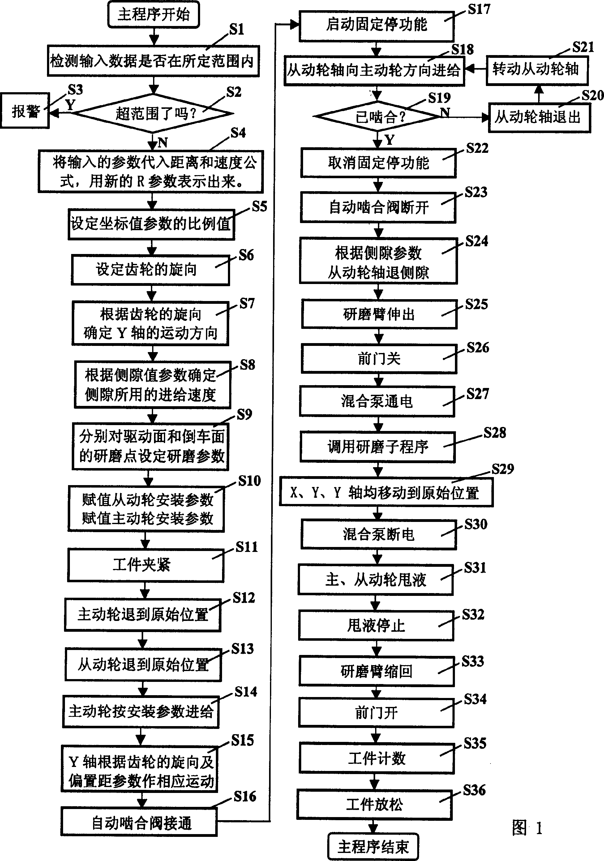
[0017] Next, the processing control method of the gear grinding machine of the present invention will be described in detail in conjunction with the accompanying drawings and specific embodiments.

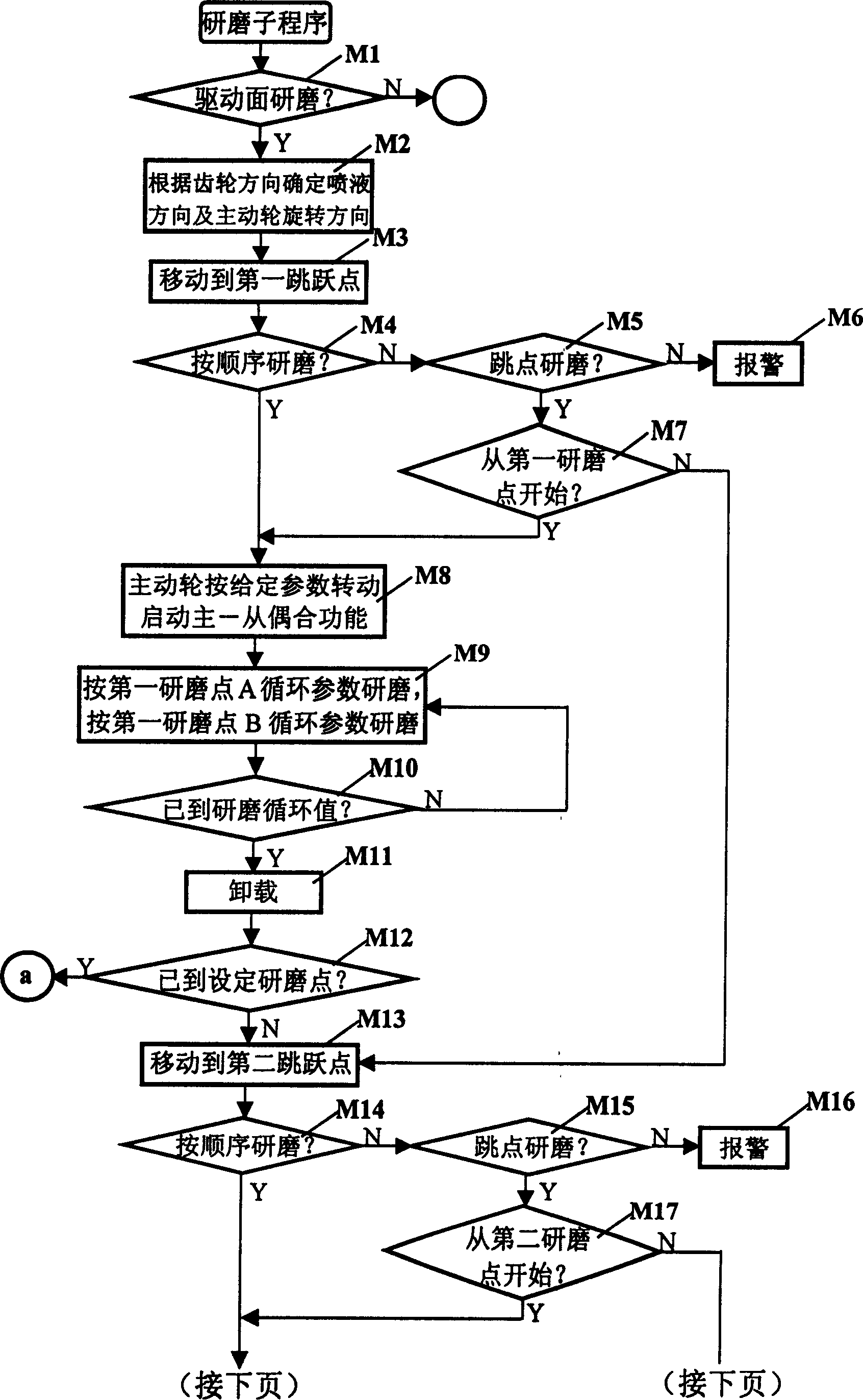
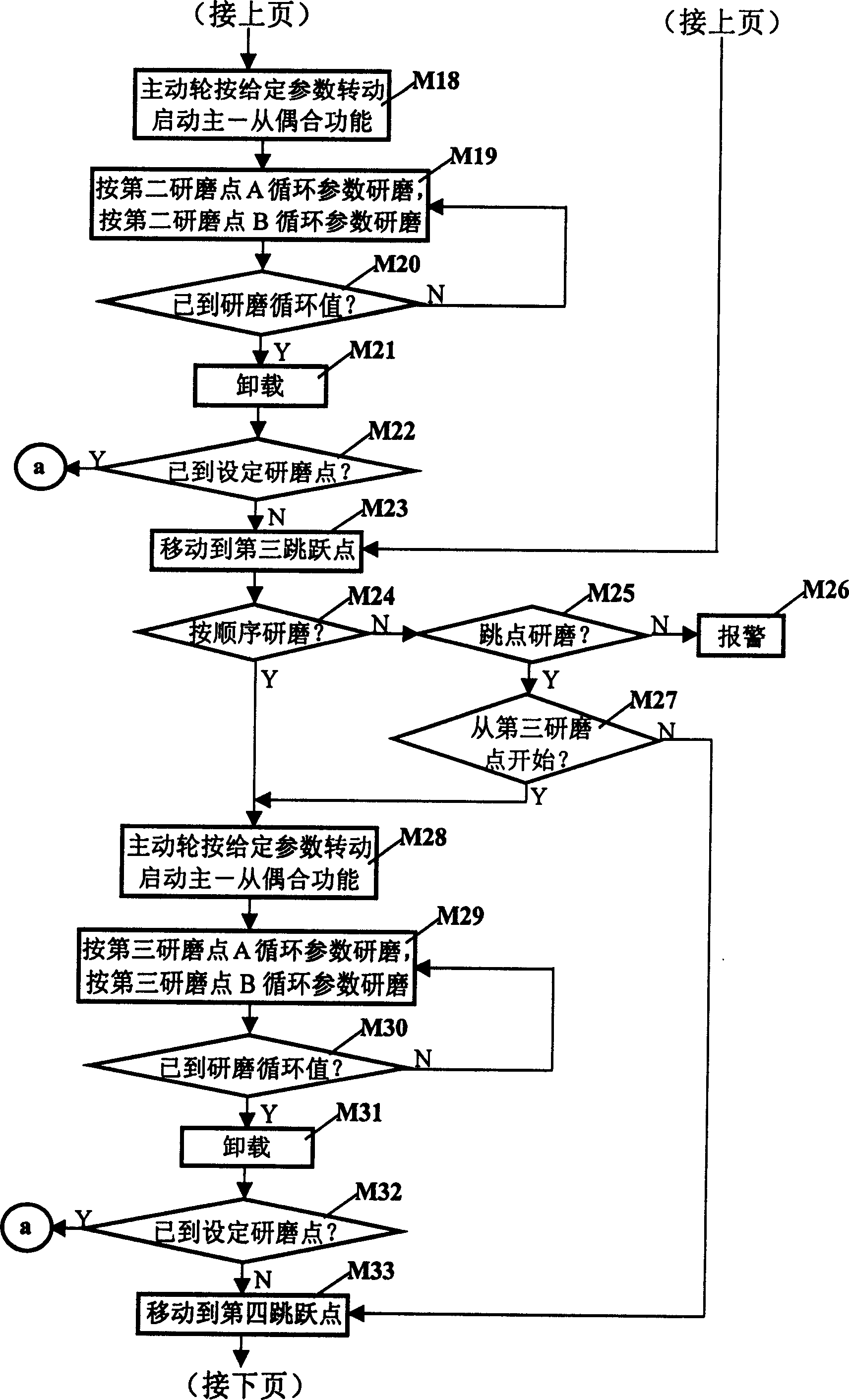
[0018] The processing control method of the gear grinding machine of the present invention includes the stage of detecting whether the input data is within the set range; the stage of setting the grinding parameters according to the input data; the stage of determining the rotation direction of the gear; The stage of feed speed and the stage of setting grinding parameters; the stage of entering the grinding preparation; the stage of meshing between the driving wheel and the driven wheel; the stage of backlash of the driven wheel shaft according to the backlash value parameter; the stage of extending the grinding arm; The stage of powering on the mixing pump by the front door; the stage of calling the grinding cycle subroutine for grinding; the stage of resetting after grinding; the ...


PUM


Abstract

The invention discloses a processing and control method of gear lapping machine, which comprises the following steps: detecting whether the input data is within the setting scale; setting the lapping parameter; affirming the gear rotary direction; obtaining the feeding speed and lapping parameter of moving side gap value; entering the lapping preparation state; slaving the shaft back side gap; extending the lapping arm; closing the front door; supplying power to the composite pump; starting the lapping circulation subprogram; resetting after lapping; breaking circuit to finish the lapping operation; counting the workpiece. The invention can select the lapping position and lapping speed of each point and loading braking torque of driven wheel freely, which realizes the needed fabricating function as long as the operator inputs or changes the fabricating parameter.

Description

technical field [0001] The invention relates to a gear grinding machine. In particular, it relates to a processing control method for a gear grinding machine that can realize required processing functions by inputting or changing parameters by an operator, and is convenient, flexible, high-precision, and ensures a better contact area. Background technique [0002] The processing method of the existing gear grinding machine can only perform two-point grinding; for example, the feed of the large wheel shaft of the existing 500 series gear grinding machine is driven by a hydraulic cylinder, and the Z axis is installed on the large wheel box. The feeding of the wheel box is driven by a solenoid valve to drive the hydraulic cylinder, which consists of three solenoid valves for the big wheel box to relax, the big wheel box to move forward, and the driven wheel box to retreat, and the driven wheel box to move forward and in place to detect the air valve, and the tooth travel switch...

Claims


Application Information

Patent Timeline
Patent Type & Authority Applications(China)
IPC IPC(8): G05B19/18B24B51/00G05B19/04G05B19/19G05B19/401
Inventor 冯玉英
Owner TIANJIN NO 1 MACHINE TOOL WORKS
Why Eureka
Try Eureka