Single crank double distance flexible type beam-pumping unit
A flexible, single-crank technology, applied in the direction of mechanical equipment, production fluid, wellbore/well components, etc., can solve the problems of high parameter adjustment and test intensity, low effective load rate, high effective load rate, etc., and achieve self-weight And the effect of reducing one-time investment, increasing effective load rate, and simple and compact structure
- Summary
- Abstract
- Description
- Claims
- Application Information
AI Technical Summary
Problems solved by technology
Method used
Image
Examples
Embodiment 1
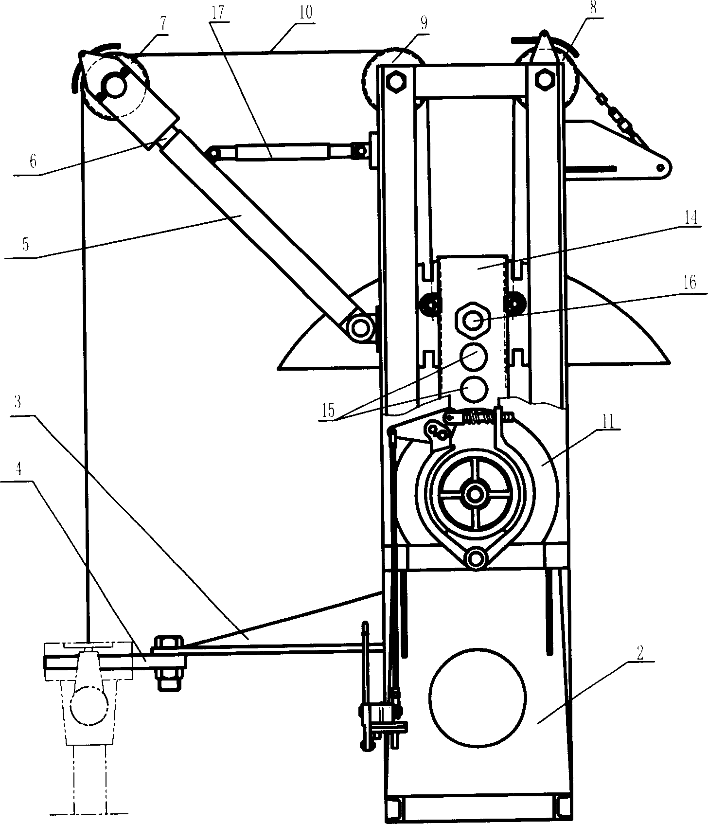
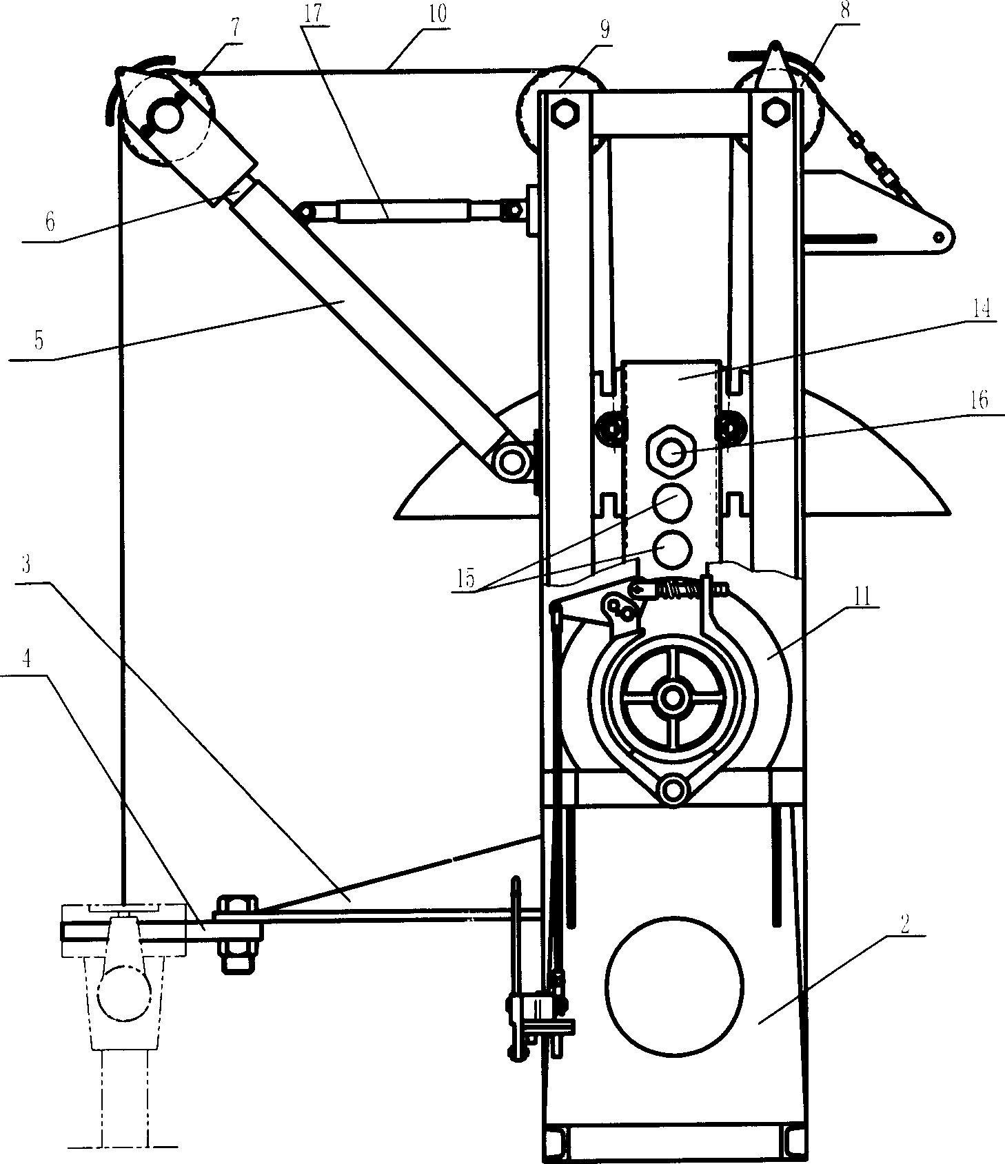
[0012] Depend on figure 1 combine figure 2 As shown, the single-crank double-range flexible pumping unit includes a motor 1 and a bracket 2. There is a connecting arm 3 on one side of the bracket 2. The connecting arm 3 is connected to the wellhead cross through bolts, and the center of gravity is transferred to the wellhead. The basic requirements of the pumping unit are reduced, and the basic construction cost of the pumping unit is greatly saved; the upper hinge of the support 2 has a telescopic cantilever 5, the cantilever 5 is connected with a cantilever shaft 6, and the shaft 6 is connected with a fixed pulley 7, and the cantilever 5 There is an adjustable pull rod 17 in the hinge between the support 2 and the wellhead. The connection between the support 2 and the wellhead can adjust the center distance between the chain 10 and the wellhead through the expansion and contraction of the cantilever shaft 6 and the pull rod 17, making the adjustment convenient; There are f...
Embodiment 2
[0014] Depend on figure 1 combine figure 2 As shown, the single-crank double-range flexible pumping unit includes a motor 1 and a bracket 2. There is a connecting arm 3 on one side of the bracket 2, and the connecting arm 3 is connected to the wellhead cross through bolts; the upper hinge of the bracket 2 has a telescopic cantilever 5. The cantilever shaft 6 is connected to the cantilever 5, and the fixed pulley 7 is connected to the shaft 6. There is an adjustable pull rod 17 at the hinge between the cantilever 5 and the bracket 2; fixed pulleys (8, 9) are respectively fixed on both sides of the upper end of the bracket 2 The motor 1 is fixed at the horizontal rear end of the middle part of the support 2, and a brake device is arranged on the motor 1 rear end shaft. The crankshaft 12 is connected, and the crank 14 has 1-3 adjustment holes 15 in the longitudinal direction, the crank pin 16 is connected in the adjustment hole 15, the crank pin 16 is connected with a movable p...
Embodiment 3
[0016] Depend on figure 1 combine figure 2 As shown, the single-crank double-range flexible pumping unit includes a motor 1 and a bracket 2. There is a connecting arm 3 on one side of the bracket 2, and the connecting arm 3 is connected to the wellhead cross through bolts; the upper hinge of the bracket 2 has a telescopic cantilever 5. The cantilever shaft 6 is connected to the cantilever 5, and the fixed pulley 7 is connected to the shaft 6. There is an adjustable pull rod 17 at the hinge between the cantilever 5 and the bracket 2; fixed pulleys (8, 9) are respectively fixed on both sides of the upper end of the bracket 2 The motor 1 is fixed at the horizontal rear end of the middle part of the support 2, and a brake device is arranged on the motor 1 rear end shaft. The crankshaft 12 is connected, and the front end of the crankshaft 12 is connected with a crank 14 through an expansion joint sleeve. The crank 14 has 1-3 adjustment holes 15 in the longitudinal direction. The ...
PUM
 Abstract
Description
Claims
Application Information
 - R&D
- Intellectual Property
- Life Sciences
- Materials
- Tech Scout
- Unparalleled Data Quality
- Higher Quality Content
- 60% Fewer Hallucinations
Browse by: Latest US Patents, China's latest patents, Technical Efficacy Thesaurus, Application Domain, Technology Topic, Popular Technical Reports.
© 2025 PatSnap. All rights reserved.Legal|Privacy policy|Modern Slavery Act Transparency Statement|Sitemap|About US| Contact US: help@patsnap.com


