Remote detection system and method

A remote detection and detection technology, which is applied in the field of detection systems, can solve problems such as the inability to detect electronic devices smoothly and conveniently, and the difficulty of detection by system chip manufacturers, so as to achieve the effect of improving development efficiency and increasing detection efficiency

Inactive Publication Date: 2006-06-28
VIA TECH INC
View PDF0 Cites 4 Cited by
  • Summary
  • Abstract
  • Description
  • Claims
  • Application Information

AI Technical Summary

Problems solved by technology

[0004] However, if the developer cannot reach the production line of the electronic device, the developer cannot test the electronic device 12 smoothly and conveniently.
Taking the electronic device 12 as a motherboard as an example, the SoC designer of the motherboard may be separated from the manufacturer of the motherboard, and it is not easy for the SoC manufacturer to assist the manufacturer in detecting problems related to the SoC on the motherboard.

Method used


Image

  • Remote detection system and method
  • Remote detection system and method
  • Remote detection system and method

Examples


Embodiment Construction

[0047] Hereinafter, the remote detection system and method according to the preferred embodiment of the present invention will be described with reference to related drawings.

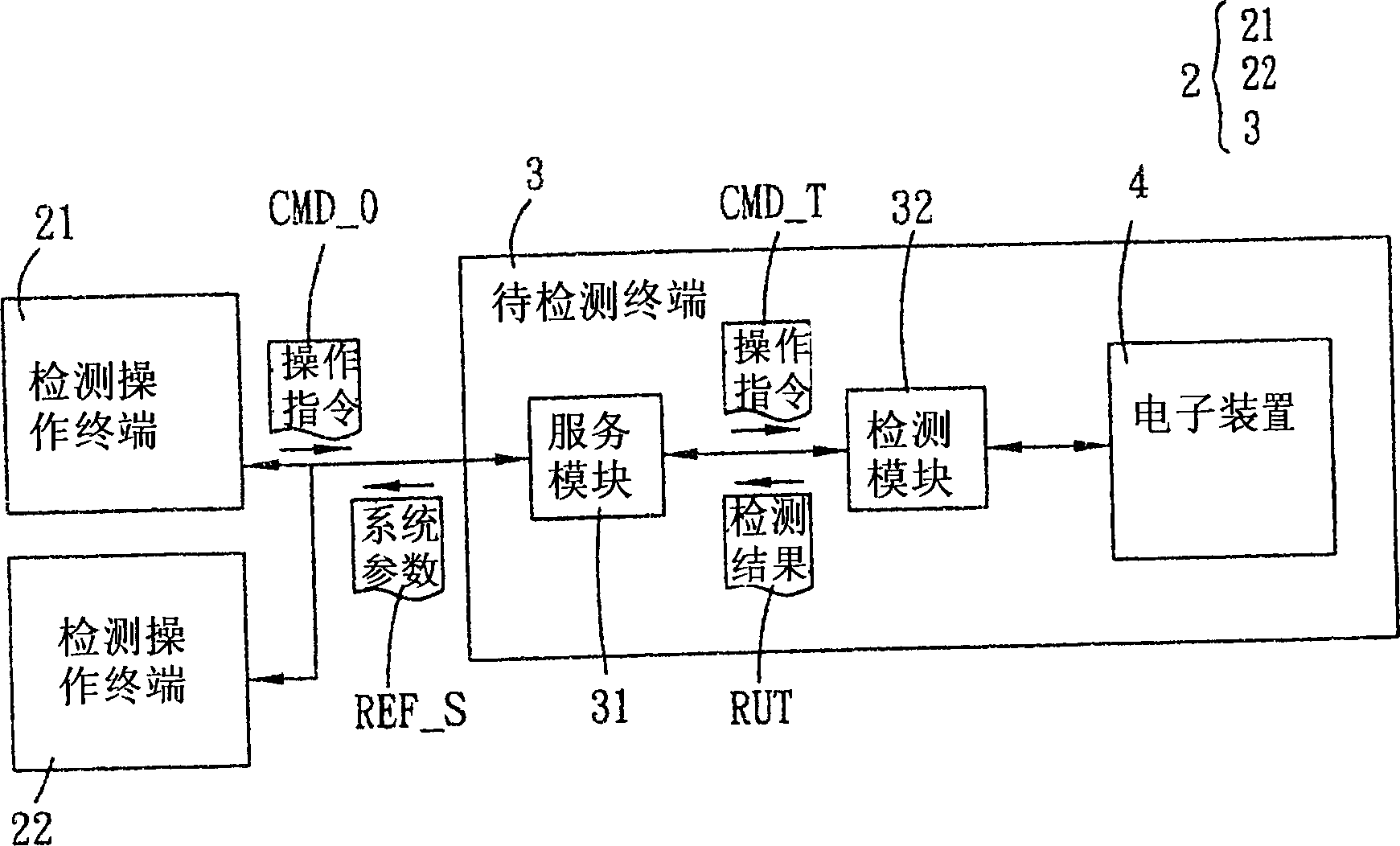
[0048] Such as figure 2 As shown, the remote detection system 2 according to the preferred embodiment of the present invention includes a detection operation terminal 21 and a terminal 3 to be tested. The terminal 3 to be tested includes a service module 31, a detection module 32, and an electronic device 4.

[0049] The service module 31 transmits the system parameter REF_S of the terminal 3 to be detected to the detection operation terminal 21, and the detection operation terminal 21 outputs an operation command CMD_O. The service module 31 receives the operation command CMD_O and generates a detection command CMD_T according to the operation command CMD_O. The detection module 32 follows The detection command CMD_T performs a detection action on the electronic device 4 to generate a detection result RU...


PUM


Abstract

A remote detection system comprises a detecting operation terminal for outputting an operation command and a terminal to be detected with a service module and a detection module. It features that at least one system parameter is transmitted from terminal to be detected to detecting operation terminal by service module and operation command is received by service module to generate a detection command, detection command is executed by detection module to generate a detection result.

Description

Technical field [0001] The present invention relates to a detection system and method, in particular to a remote detection system and method. Background technique [0002] Generally speaking, a hardware device is composed of several components. If the hardware device is to be executed normally, the components need to be coordinated and coordinated with an appropriate interface such as a driver. [0003] Such as figure 1 As shown, when the test system 11 tests the electronic device 12, the developer must use the test system 11 on site to view the set value (such as the driver) of the electronic device 12 or the value of the register of each processing component in the electronic device 12. [0004] However, if the developer cannot reach the production line of the electronic device, the developer cannot test the electronic device 12 smoothly and conveniently. Taking the electronic device 12 as a motherboard as an example, the system chip designer of the motherboard may be separate...

Claims


Application Information

Patent Timeline
Patent Type & Authority Applications(China)
IPC IPC(8): G01R31/00G01R31/317G06F11/22
Inventor 赖格升
Owner VIA TECH INC
Why Eureka
Try Eureka