Self-reconstruction plasma antenna

A plasma antenna and plasma technology, applied in the direction of antenna support/installation device, etc., can solve the problems of large scattering area, inability to electrically adjust the length, and high mutual interference, and achieve low noise performance, mutual interference suppression, and good axial direction. The effect of uniformity

Inactive Publication Date: 2006-06-28
SHANGHAI JIAO TONG UNIV
View PDF1 Cites 15 Cited by
  • Summary
  • Abstract
  • Description
  • Claims
  • Application Information

AI Technical Summary

Problems solved by technology

The antenna overcomes a series of shortcomings such as large scattering area, high mutual interference, and non-electrical adjustment of the length of the previous metal conductor antenna.

Method used


Image

  • Self-reconstruction plasma antenna
  • Self-reconstruction plasma antenna
  • Self-reconstruction plasma antenna

Examples


Embodiment Construction

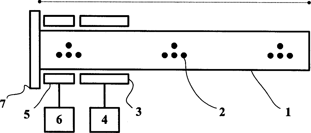
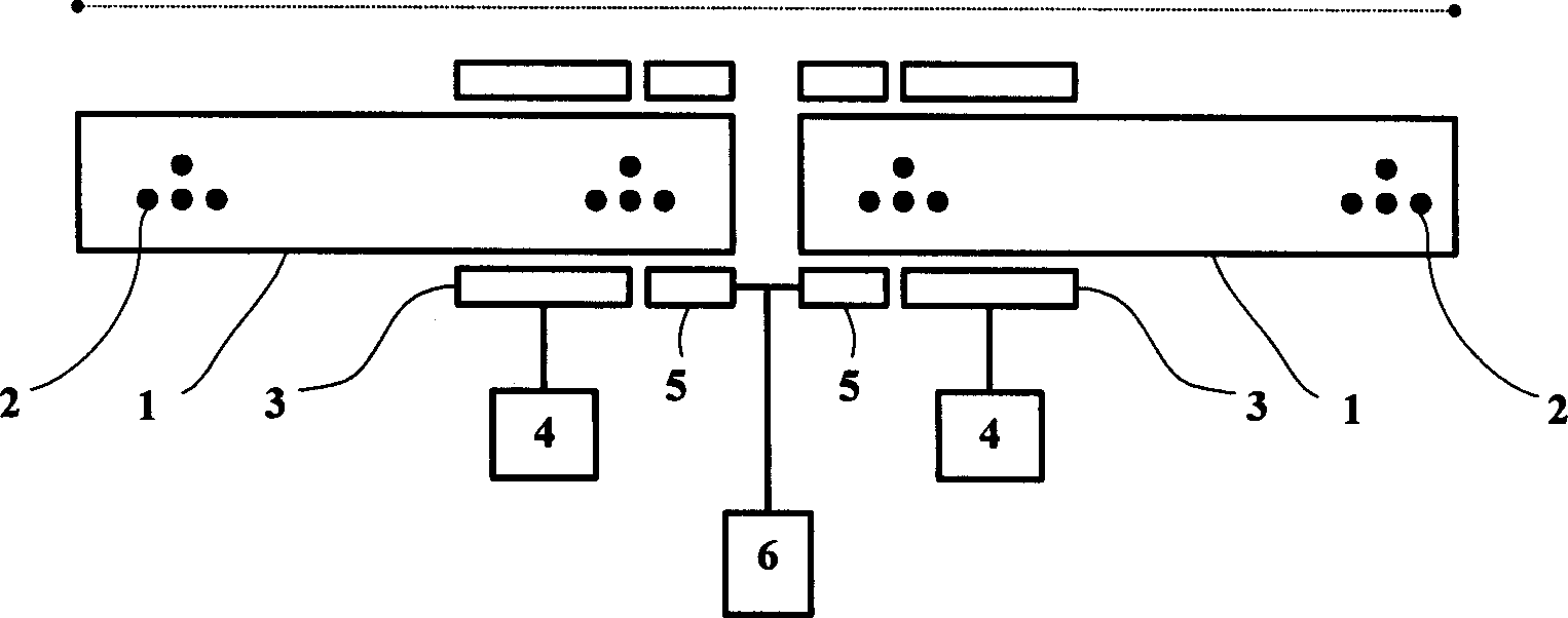
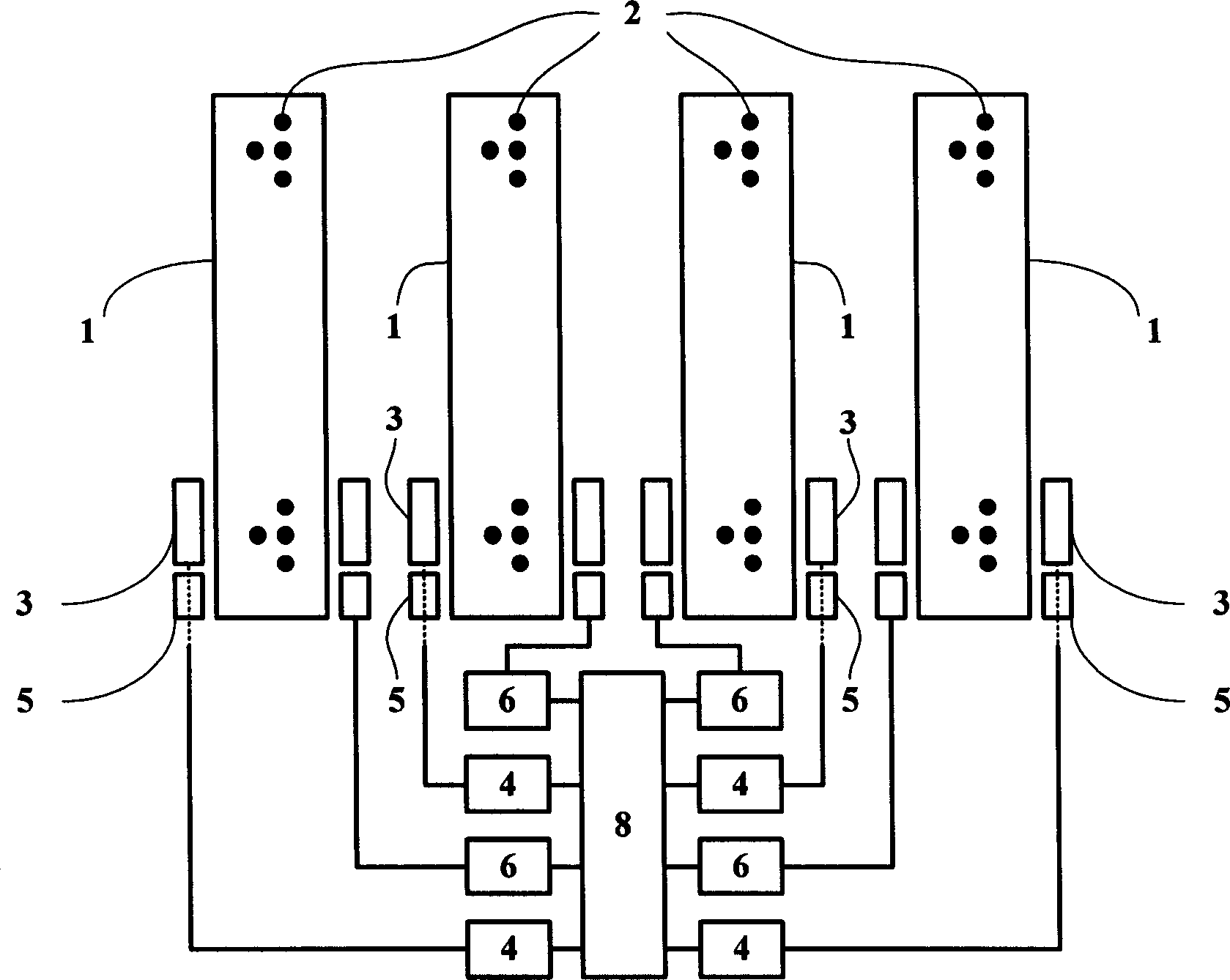
[0014] Such as figure 1 As shown, the present invention includes: a cylindrical container 1 , an inert gas 2 , a radio frequency excitation antenna 3 , a radio frequency excitation source 4 , a signal coupler 5 , a feed port 6 , and a ground plate 7 . The cylindrical container 1 is filled with an inert gas 2. When the gas is ionized, plasma can be formed. At this time, the plasma column in the cylindrical container can be used as a conductor of the antenna to emit or receive electromagnetic waves. The radio frequency excitation source 4 and the radio frequency excitation antenna 3 are used to excite and maintain the plasma. The radio frequency excitation antenna 3 is placed inside or outside the cylindrical container, and its lead wire is connected to the radio frequency excitation source 4 . When the radio frequency excitation source 4 is working, a radio frequency spiral electric field will be generated around the radio frequency excitation antenna 3, and the gas in the cyli...


PUM


Abstract

This invention relates to a self-restructing plasma antenna including a column container, inert gases, a RF excitation antenna, a RF excitation source, a signal coupler, a feeding port and an earth plate characterizing that the column container is filled with inert gases, the source and the antenna are used in exciting and maintaining the plasma, in which, the excitation antenna is set in the inside or outside of the column container, its lead out wire is connected with the RF excitation source, the signal coupler is used to couple the signal to the plasma antenna set out of the container, the lead out wire is connected with the internal conductor of the feeding port and the outer conductor is connected with the earth plate.

Description

technical field [0001] The invention relates to an antenna used in the technical field of communication, in particular to a self-reconfigurable plasma antenna. Background technique [0002] A traditional antenna is defined as a metal device for transmitting and receiving radio waves, or a metal conductor with a certain shape and structure. Therefore, the antenna design in the past has focused on the geometric structure, physical size, metal material selection, electrical coupling structure, multi-antenna design, and / or electromagnetic waveform characteristics of the antenna, such as the transmission wavelength, transmission efficiency, and transmission waveform of the antenna during operation. reflection and more. The size of an antenna is closely related to its radiation efficiency. In order to radiate energy as efficiently as possible, the length of the antenna is usually half or quarter wavelength. In this sense, once the size of an antenna using metal as a conductor i...

Claims


Application Information

Patent Timeline
Patent Type & Authority Applications(China)
IPC IPC(8): H01Q1/26
Inventor 袁斌蒋磊赵磊
Owner SHANGHAI JIAO TONG UNIV
Why Eureka
Try Eureka